Inkjet printing apparatus

a printing apparatus and inkjet technology, applied in printing and other directions, can solve the problems of complex construction around the nozzle head, large space occupied by the entire inkjet printing apparatus, defective ink discharge from the ink discharge nozzle, etc., and achieve the effect of constant height relationship and simple construction

Active Publication Date: 2012-08-02
DAINIPPON SCREEN MTG CO LTD
View PDF3 Cites 37 Cited by
  • Summary
  • Abstract
  • Description
  • Claims
  • Application Information

AI Technical Summary

Benefits of technology

[0031]According to such inkjet printing apparatus, an extremely simple construction is provided to maintain a constant height relationship between the inkjet heads and subtank. Thus, ink can always be discharged accurately from the inkjet heads.

Problems solved by technology

This gives rise to a problem of requiring a large space occupied by the entire inkjet printing apparatus.
In such an inkjet printing apparatus, ink mist produced by ink scattering at a time of discharge, and paper powder produced from printing paper which is a recording medium, could adhere to ink discharge nozzle forming surfaces of the inkjet heads, thereby causing a defective ink discharge from the ink discharge nozzles.
However, the inkjet printing apparatus disclosed in Japanese Unexamined Patent Publication No. 2001-18406 goes through a complicated operation to move the nozzle heads to the nozzle head wiping position, then move the nozzle heads upward to an ink receiving member wiping position, and further return the nozzle heads to a printing position.
This poses a problem in that the construction around the nozzle heads becomes complicated.
Such positioning operation is inefficient, and the construction around the nozzle heads also becomes complicated.
This is because, when an ink tank and the inkjet heads are directly connected without providing a subtank, there arises a problem of failing to discharge the ink steadily from the inkjet heads due to an amount of ink stored in the ink tank and other factors.
On the other hand, the inkjet heads are movable up and down in order to perform a printing operation and a maintenance operation, which results in a difference in height between the inkjet heads and subtank.
This makes an accurate discharge of ink impossible, and causes printing failures such as missing nozzle.
However, changing the height of the intermediate tank gives rise to a problem of making control of the ink discharge difficult, and only making uniform ink discharge impossible.

Method used


Image

  • Inkjet printing apparatus
  • Inkjet printing apparatus
  • Inkjet printing apparatus

Examples


Embodiment Construction

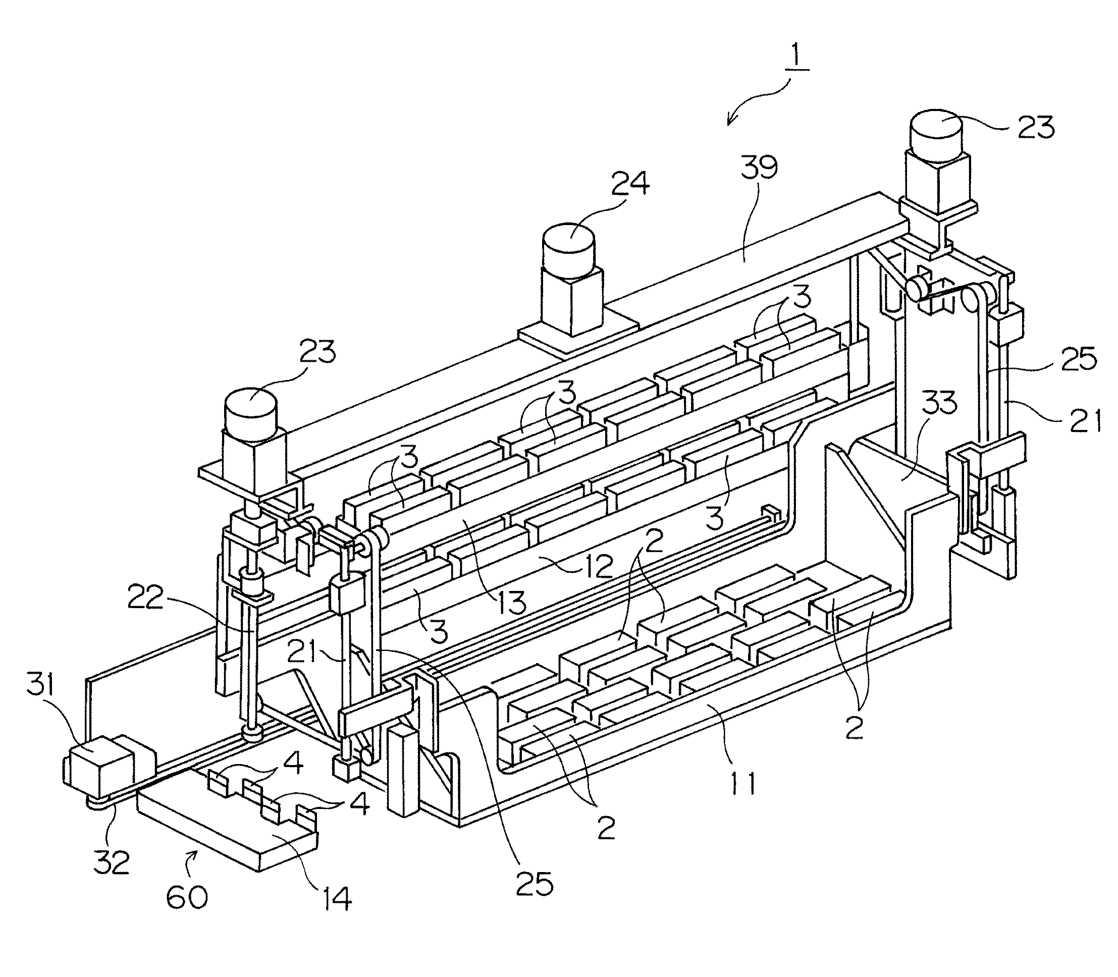
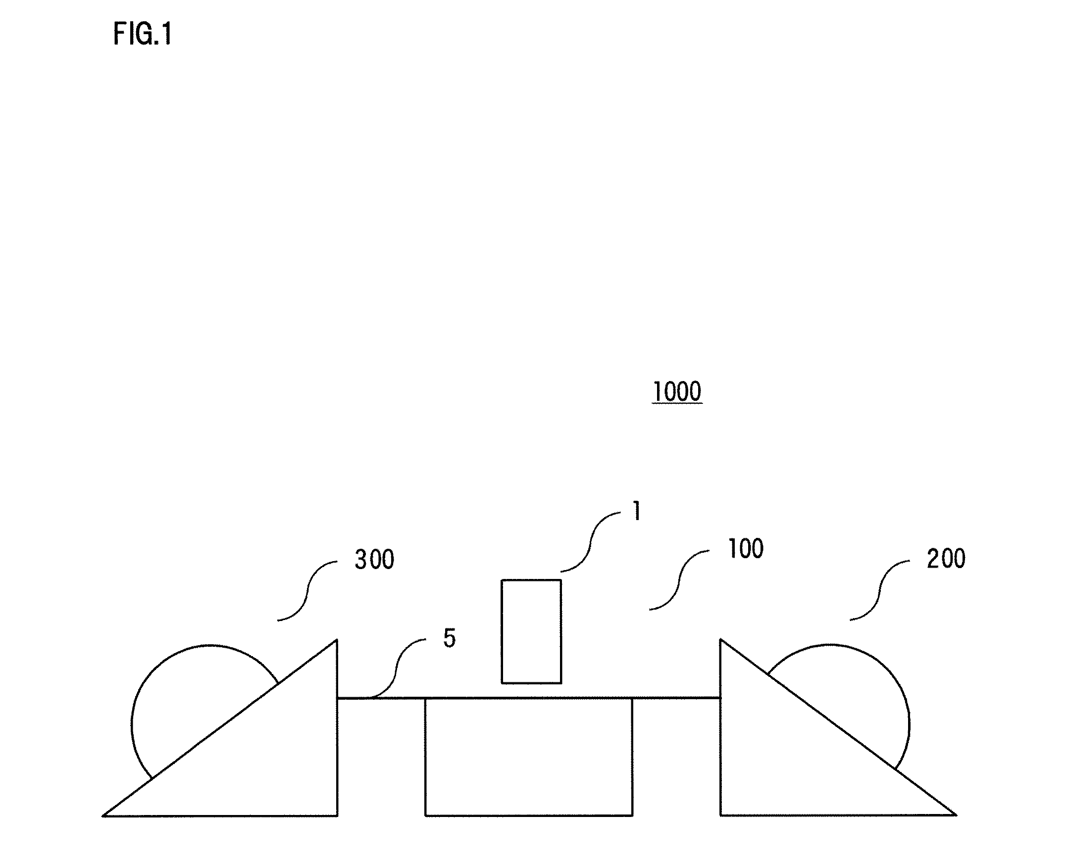
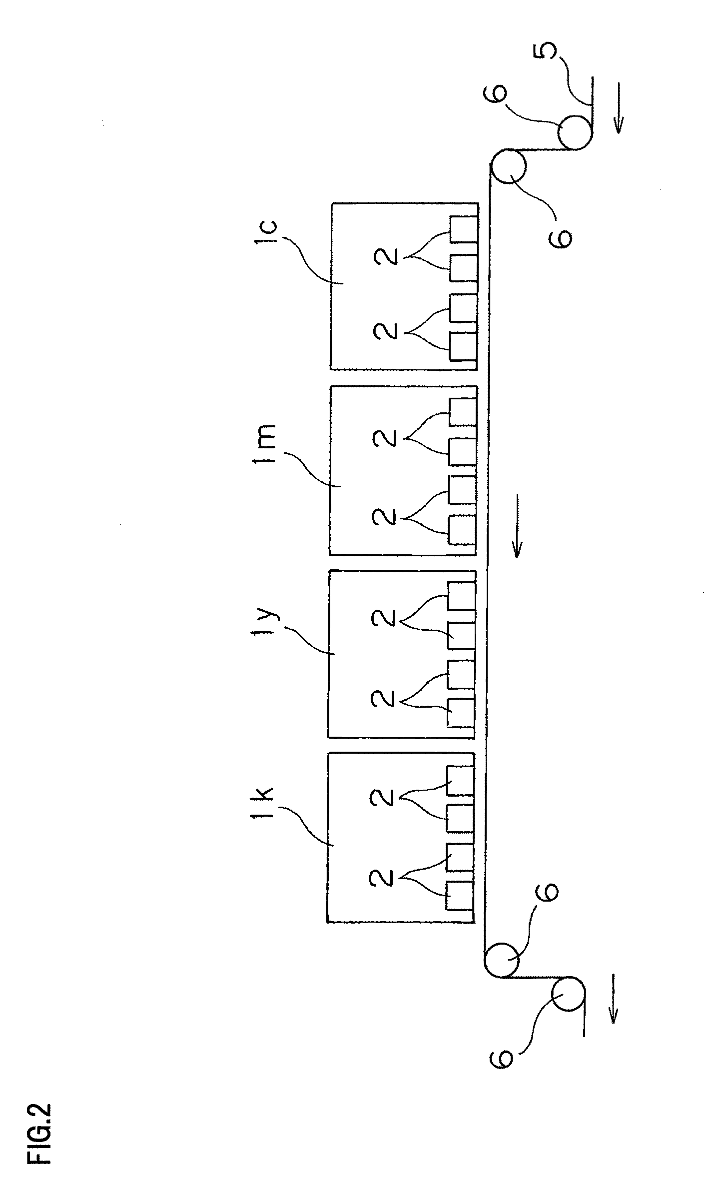
[0065]Embodiments of this invention will be described hereinafter with reference to the drawings. FIG. 1 is a schematic view of a printing system 1000 incorporating an inkjet printing apparatus 100 according to this invention. FIG. 2 is a schematic view of a principal portion of the inkjet printing apparatus 100.

[0066]The printing system 1000 shown in FIG. 1 includes the inkjet printing apparatus 100, a recording medium feeding apparatus 200 and a recording medium takeup apparatus 300.

[0067]The recording medium feeding apparatus 200 stores printing paper 5 acting as recording medium in the form of a roll, and feeds the printing paper 5 for recording thereon in the inkjet printing apparatus 100.

[0068]The recording medium takeup apparatus 300 takes up the printing paper 5 recorded in the inkjet printing apparatus 100, for storage in the form of a roll.

[0069]The printing paper 5 is a recording medium in the form of a web having a predetermined width. This printing system 1000 can recor...


PUM


Abstract

An inkjet printing apparatus 100 includes an inkjet head holder 11 holding inkjet heads 2, and a pair of head cap holders 12 and 13 holding head caps 3. When the inkjet head holder 11 is in a raised position, the head cap holders 12 and 13 are arranged as horizontally juxtaposed in a capping position, where the respective inkjet heads 2 and the respective head caps 3 are opposed to each other, below the inkjet head holder 11. When the inkjet head holder 11 is in a lowered position, the head cap holders 12 and 13 are arranged as vertically superposed in a withdrawn position laterally of a vertical movement area of the inkjet head holder 11.

Description

BACKGROUND OF THE INVENTION[0001]1. Field of the Invention[0002]This invention relates to an inkjet printing apparatus for performing printing by moving a printing medium relative to inkjet heads.[0003]2. Description of the Related Art[0004]What is called a one-pass inkjet printing apparatus is known as an inkjet printing apparatus for outputting a large number of prints at high speed. This printing apparatus includes a print head having a plurality of inkjet heads to secure a discharge range substantially corresponding to a width in a primary scanning direction perpendicular to a transport direction of a recording medium (secondary scanning direction), and carries out recording by discharging ink as necessary to the recording medium transported.[0005]In such an inkjet printing apparatus, head caps are used for the purpose of preventing drying of the inkjet heads. In order to prevent drying and contamination of areas adjacent ink discharge portions of the inkjet heads, these head ca...

Claims


Application Information

Patent Timeline
Patent Type & Authority Applications(United States)
IPC IPC(8): B41J2/165
CPCB41J2/16511B41J2/16505
Inventor IWASA, HIROSHIFUCHIOKA, HIROYUKIKATAYAMA, TAKESHINAOE, RYOICHI
Owner DAINIPPON SCREEN MTG CO LTD
Why Eureka
Try Eureka