
Method for channel state measurement in multi-mode multi-hop wireless networks

a wireless network and multi-mode technology, applied in the field of communication networks, can solve the problem of not finding solutions to the wireless channel state measurement problem, and achieve the effect of reducing the complexity of measuremen

Active Publication Date: 2012-08-02
INTERDIGITAL CE PATENT HLDG
View PDF10 Cites 3 Cited by
  • Summary
  • Abstract
  • Description
  • Claims
  • Application Information

AI Technical Summary

Benefits of technology

[0013]Finally, in addition to the protocol, and in case where the system supports a large number of Tx / Rx modes, the inventors also propose methods to reduce measurement complexity by reducing the number of modes that need to be measured.

Problems solved by technology

Currently there exist no solutions that address the wireless channel state measurement problem in a general multi-mode, multi-hop wireless network environment.

Method used


Image

  • Method for channel state measurement in multi-mode multi-hop wireless networks
  • Method for channel state measurement in multi-mode multi-hop wireless networks
  • Method for channel state measurement in multi-mode multi-hop wireless networks

Examples


Embodiment Construction

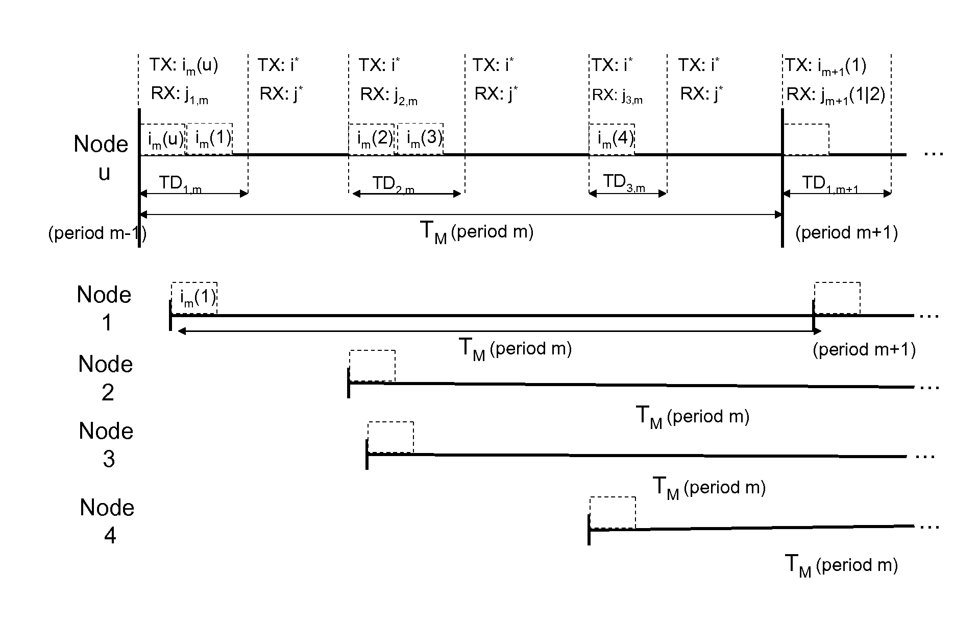
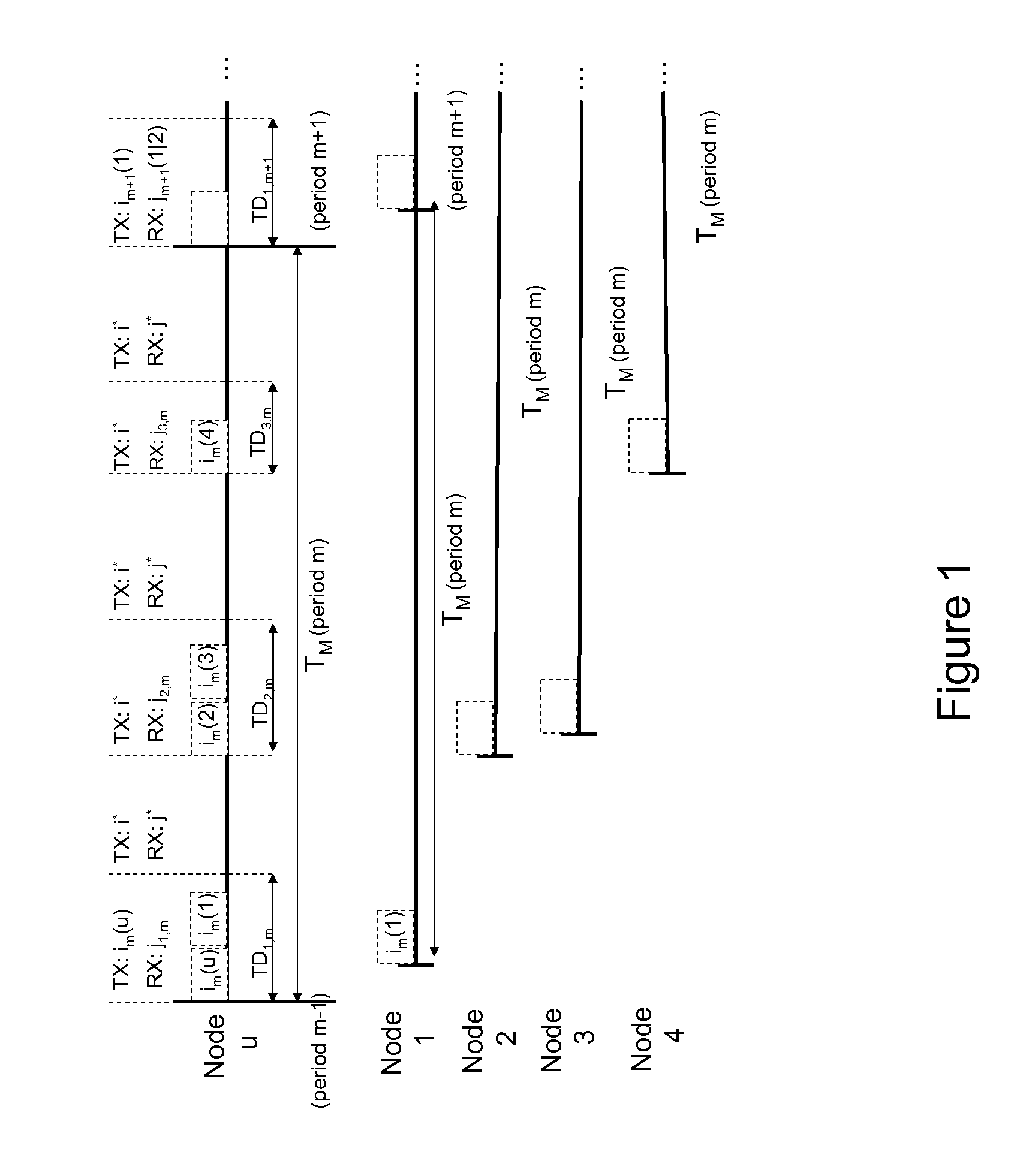
[0038]The wireless network is represented by a directed graph G=(V,E) where V is a set of N nodes in the network and EV2 is a set of uni-directional links between pairs of nodes. More precisely, the link (u,v)εE exists between node pair u and v, if data can be delivered from u to v with a delivery ratio above a threshold (PRRthresh) when the link operates at the lowest bit rate supported by the underlying physical layer. This ensures that each link in the network can carry data using at least one of the possible bit rates. For each node u, we define the set of its neighbor nodes N(u) as all the nodes vεV for which (v,u)εE, i.e. node u can receive packets from according to the definition above.

[0039]The system operates with a set of M Tx / Rx modes M={(im, jm), m=1, . . . , M}, where im, and jm take values from the set K={0, 1, . . . , K}. In wireless networks with smart antennas, each Tx / Rx mode corresponds to a distinct antenna pattern on the wireless link, formed when transmitter an...


PUM


Abstract

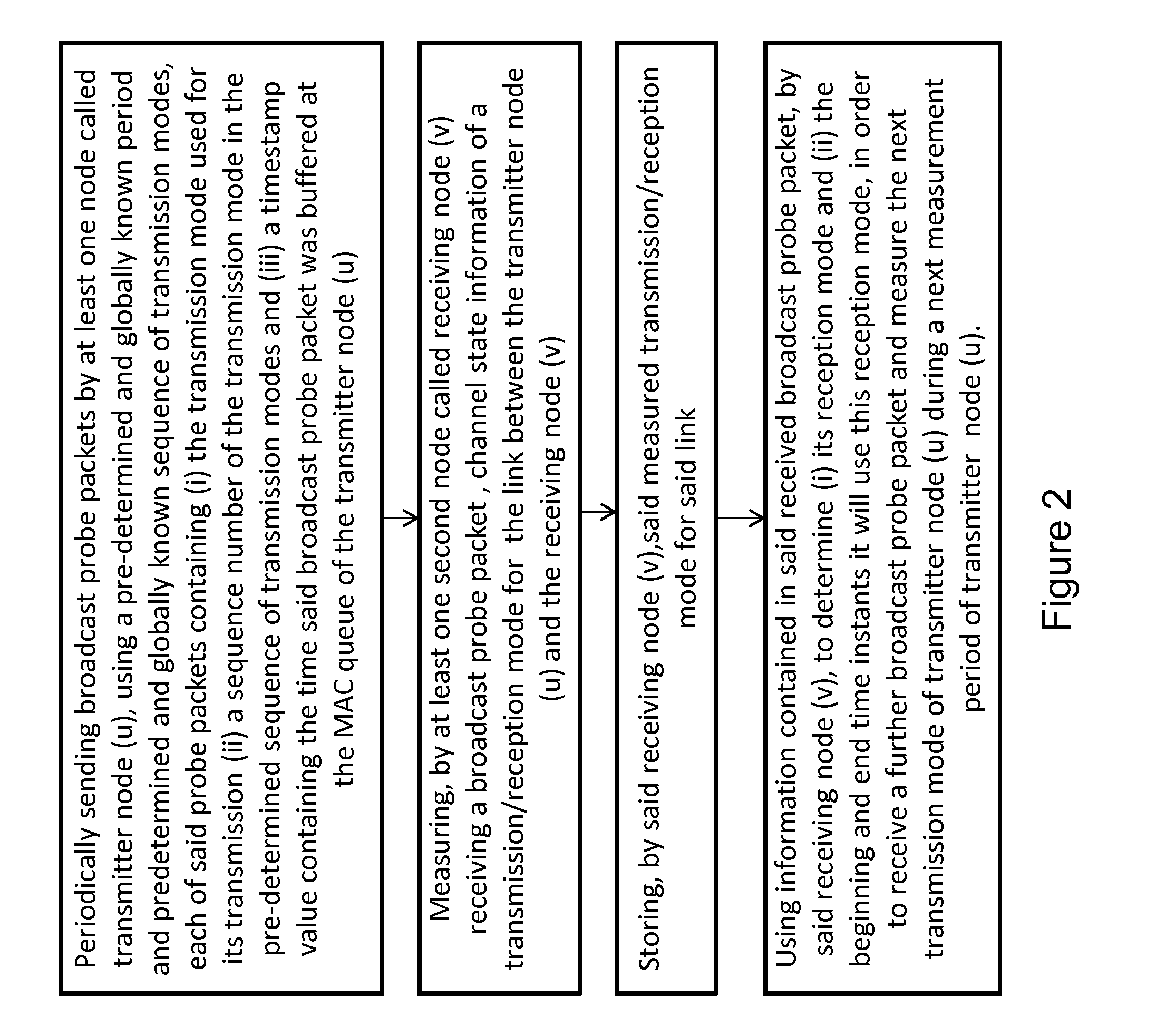
The invention concerns a method for measuring channel state information of multiple transmission / reception modes in a wireless network comprising a plurality of nodes, said modes being defined by frequency channels and / or antenna patterns, said wireless network comprising a MAC (Media Access Control) layer and every node comprising at least one MAC queue, comprising the steps of: periodically sending broadcast probe packets by at least one node called transmitter node, using a pre-determined and globally known period and predetermined sequence of transmission modes, each of said probe packets containing the transmission mode used for its transmission a sequence number of the transmission mode in the pre-determined sequence of transmission modes and a timestamp value containing the time said broadcast probe packet was buffered at the MAC queue of the transmitter node; measuring, by at least one second node called receiving node receiving a broadcast probe packet, channel state information of a transmission / reception mode for the link between the transmitter node and the receiving node; storing, by said receiving node, said measured transmission / reception mode for said link; using information contained in said received broadcast probe packet, by said receiving node, to determine its reception mode and the beginning and end time instants it will use this reception mode, in order to receive a further broadcast probe packet and measure the next transmission mode of transmitter node, during a next measurement period of transmitter node.

Description

FIELD OF THE INVENTION[0001]The present invention pertains to the field of communication networks.[0002]The present invention more particularly relates to a method for channel state measurement in multi-mode multi-hop wireless networks.BACKGROUND OF THE INVENTION[0003]The present invention introduces a distributed protocol for measurement of the channel state information of multiple transmission / reception (Tx / Rx) modes (defined by frequency channels or antenna patterns) on all wireless links in a multi-hop wireless network. The protocol does not need to be integrated with the Medium Access Control (MAC) protocol but can operate at a higher layer (e.g. network layer) of the OSI protocol stack. This makes the protocol general and independent of the wireless technology being used.[0004]Currently there exist no solutions that address the wireless channel state measurement problem in a general multi-mode, multi-hop wireless network environment.[0005]Channel state measurement mechanisms f...

Claims


Application Information

Patent Timeline
Patent Type & Authority Applications(United States)
IPC IPC(8): H04W24/00
CPCH04W88/06H04W24/10
Inventor SALONIDIS, THEODOROSSUBRAMANIAN, ANAND PRABHULUNDGREN, HENRIKTOWSLEY, DON
Owner INTERDIGITAL CE PATENT HLDG
Learn More