
Drill bit

a drill bit and drill bit technology, applied in the field of drill bits, can solve the problems of difficult control of drill bits and users' choice, and achieve the effect of smooth operation and fast cutting performance of single-flange drill bits

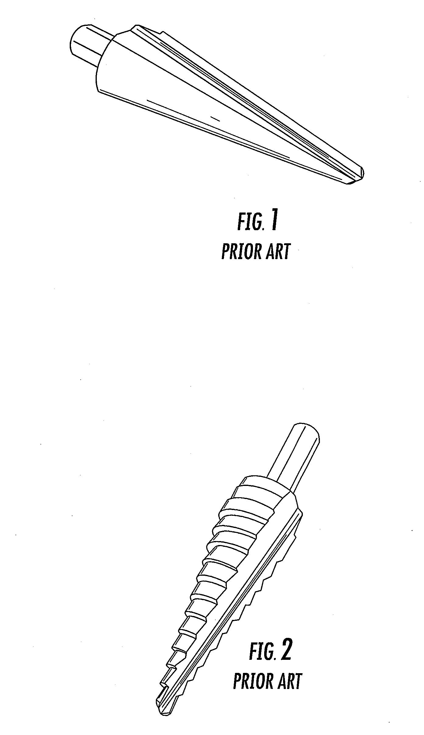
Inactive Publication Date: 2012-08-02
WHITE CHRISTOPHER L
View PDF10 Cites 33 Cited by
  • Summary
  • Abstract
  • Description
  • Claims
  • Application Information

AI Technical Summary

Benefits of technology

"The patent describes a drill bit that combines the fast cutting performance of a dual flute drill bit with the smooth operation of a single flute drill bit. The drill bit has a conical shape with first and second cutting flutes along its length. The first flute has a first cutting edge and the second flute has a second cutting edge that is offset to create a cutting angle that reduces chatter. This design allows for smoother drilling and reduces the likelihood of damage to the substrate."

Problems solved by technology

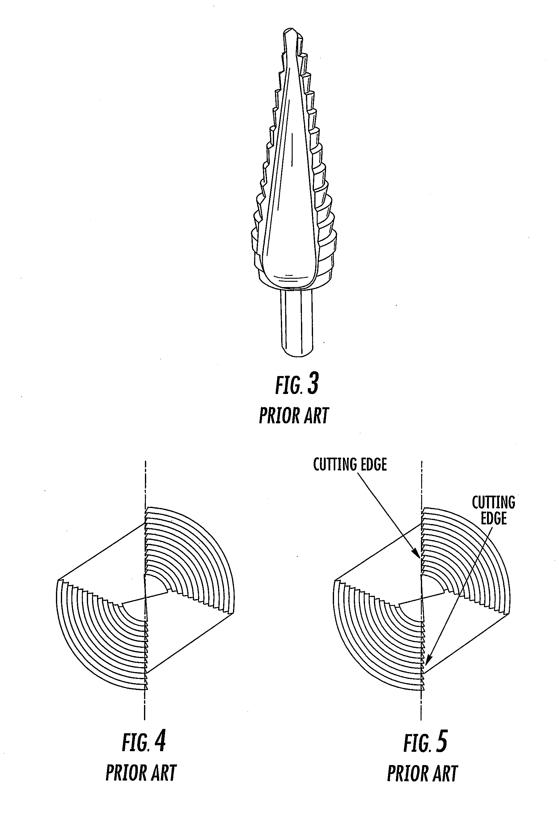
For example, the drill bit of FIG. 3 is known to provide a very smooth cutting operation, but unfortunately, is also very slow due to the single cutting flute.
The drill bit of FIG. 4 is known to provide faster cutting performance than the drill bit of FIG. 3, but unfortunately, is known to have excessive amounts of chatter, thereby making the drill bit difficult to control.
As a result, users are often forced to choose between the speed of a dual flute drill bit or the control of the single flute drill bit.

Method used


Image

  • Drill bit
  • Drill bit
  • Drill bit

Examples


Embodiment Construction

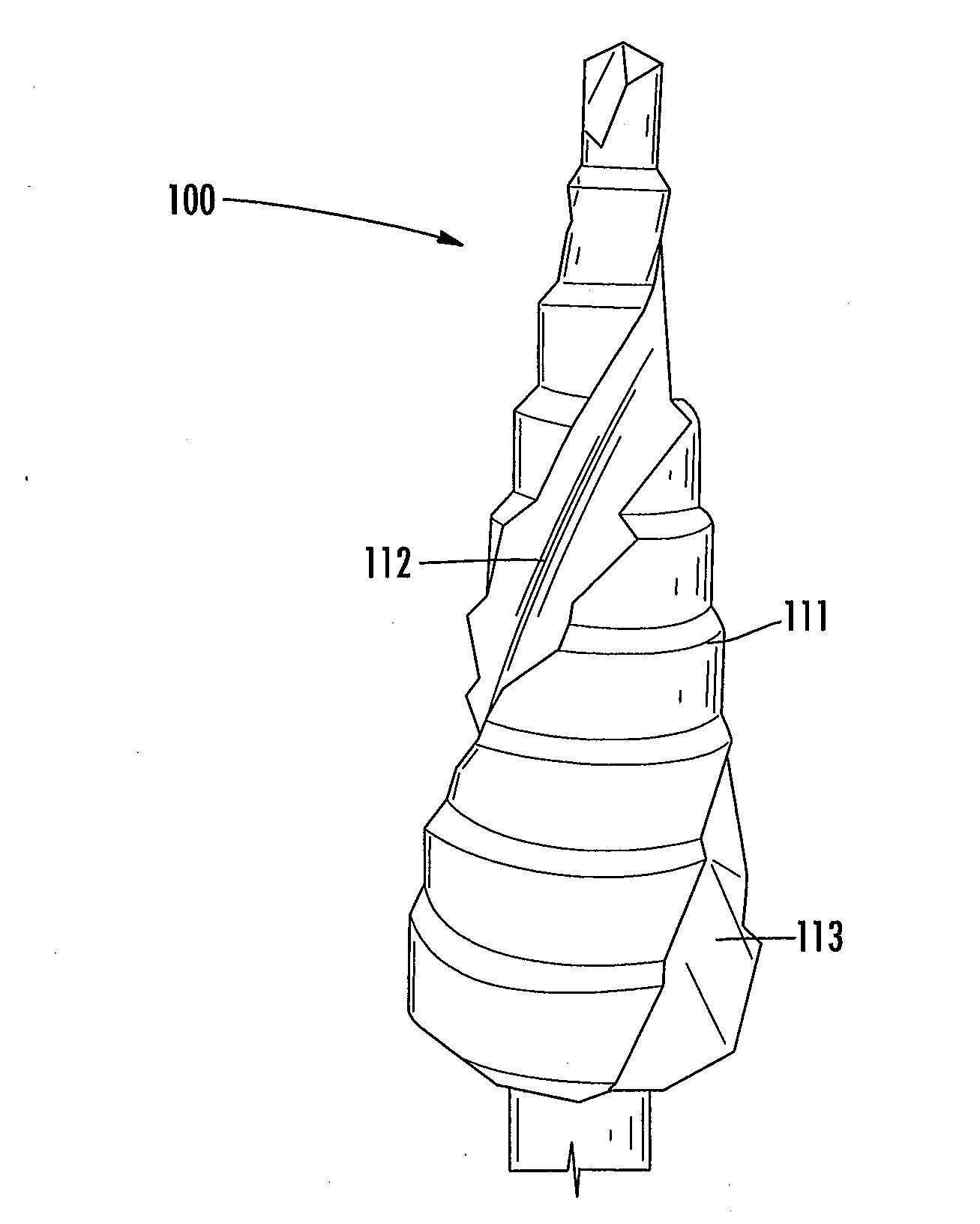
[0020]Referring to FIGS. 6-8, a multi-flute, cone-shaped drill bit according to an embodiment of the invention is shown generally at 10. As shown, the drill bit 10 includes a plurality of steps 11, increasing in diameter along the length of the drill bit 10 from the tip 15 of the drill bit 10 to the shank 18 of the drill bit 10, for controlling the depth and diameter of a hole being drilled in a substrate and a pair of cutting flutes 12 and 13, running along the length of the drill bit 10 for cutting a hole into a substrate. As shown, the flutes 12 and 13 are disposed at angles between 2 and 7 degrees off parallel to the drill bit's axis, FIG. 8. It should be appreciated that while only two cutting flutes are shown, the drill bit 10 may have additional cutting flutes. It should also be appreciated that the flutes 12 and 13 may be disposed at various angles relative to the axis of the drill bit 10. It should be appreciated that the invention works with smooth outer surface bits as we...


PUM

PropertyMeasurementUnit
angleaaaaaaaaaa
angleaaaaaaaaaa
cutting angleaaaaaaaaaa

Abstract

A drill bit for cutting successively larger holes in a substrate includes a conically-shaped body having first and second cutting flutes extending along the length of the body. The first cutting flute includes a first cutting edge and the second cutting flute includes a second cutting edge. The first and second cutting edges are offset relative to each other to create a cutting angle adapted to reduce chatter.

Description

[0001]This application claims the benefit of Provisional Application No. 61 / 438,006 filed on Jan. 31, 2011.BACKGROUND OF THE INVENTION[0002]The present invention relates generally to a drill bit, and more particularly to a drill bit designed to create successively larger holes in a substrate.[0003]Having the ability to create various sized holes with a single drill bit is advantageous in that it eliminates the need to use multiple drills or to constantly change out drill bits. As a result, cone-shaped drill bits were designed. The cone-shaped drill bits include at least one cutting edge and allow the user to start with a small hole and gradually increase the diameter of the hole by increasing the depth of the drill bit within the substrate being drilled.[0004]When a specific diameter of hole is desired, a user must be careful to control the depth of the cone-shaped drill bits so that the diameter of the hole is not made too big. This is particularly true of cone-shaped bits that hav...

Claims


Application Information

Patent Timeline
Patent Type & Authority Applications(United States)
IPC IPC(8): B23B51/02
CPCB23B51/0081Y10T408/906B23B2251/282B23B51/009
Inventor WHITE, CHRISTOPHER L.
Owner WHITE CHRISTOPHER L
Learn More