Cmc turbine engine blades and a rotor wheel for a turbine engine and a turbine engine integrating them

a technology of turbine engine blades and rotor wheels, which is applied in the direction of rotors, marine propulsion, vessel construction, etc., can solve the problem that the blades made of cmc cannot be used

Inactive Publication Date: 2012-08-02
SN DETUDE & DE CONSTR DE MOTEURS DAVIATION S N E C M A
View PDF5 Cites 51 Cited by
  • Summary
  • Abstract
  • Description
  • Claims
  • Application Information

AI Technical Summary

Benefits of technology

[0008]An object of the invention is to provide a solution to the problem of damping the vibratory stresses to which the blades of rotor wheels of a turbine engine are subjected.

Problems solved by technology

Turbine engine blades are exposed to excitations that are produced by their environment, in particular the wake effect from nozzles (stationary vanes) or by unbalance.
Such a solution cannot be envisaged for blades made of CMC because of the difficulty firstly in binding a metal coating to a CMC material, and secondly of guaranteeing that said binding is long-lasting, given the difference between the coefficients of thermal expansion of the metal coating and of the CMC material.

Method used


Image

  • Cmc turbine engine blades and a rotor wheel for a turbine engine and a turbine engine integrating them
  • Cmc turbine engine blades and a rotor wheel for a turbine engine and a turbine engine integrating them
  • Cmc turbine engine blades and a rotor wheel for a turbine engine and a turbine engine integrating them

Examples


Embodiment Construction

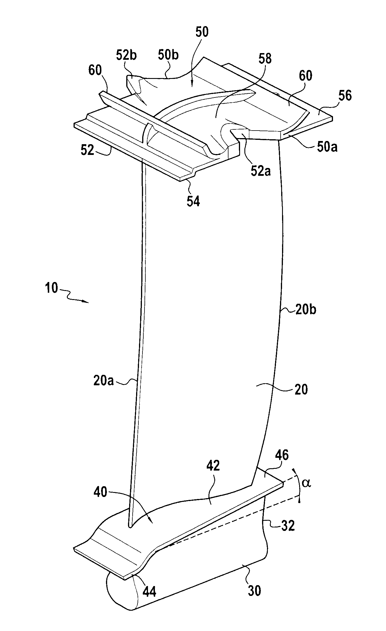
[0035]The invention is applicable to various types of turbine engine blade, in particular compressor blades or turbine blades for various spools of a gas turbine, e.g. a blade for a rotor wheel of an LP turbine, such as the blade 10 of FIG. 1.

[0036]In well-known manner, the blade 10 comprises an airfoil 20, a root 30 formed by a portion of greater thickness, e.g. presenting a bulb-shaped section, and extended by a tang 32, an inner platform 40 situated between the tang 30 and the airfoil 20 and an outer platform 50 in the vicinity of the free end of the airfoil 20.

[0037]The airfoil 20 extends in a longitudinal direction between the inner platform 40 and the outer platform 50, and in cross-section it presents a curved profile of varying thickness between its leading edge 20a and its trailing edge 20b. The root 30 is extended by the tang 32 so as to connect to the inner (or bottom) face of the inner platform 40.

[0038]At its radially inner end, the airfoil 20 is connected to the outer ...


PUM


Abstract

A rotor wheel of a turbine engine includes a plurality of CMC blades each having a first portion constituting a blade airfoil and root and made as a single piece with a second portion forming an outer platform. The blades are held under twisting prestress by mutual engagement via contact zones between the outer platforms of adjacent blades, and the contact zones that are situated on opposite sides of the outer platform of a blade are defined by at least one insert that is integrated in the outer platform and that is, for example, made of a carbon-based material.

Description

BACKGROUND OF THE INVENTION[0001]The invention relates to turbine engine blades made of ceramic matrix composite (CMC) material, i.e. comprising fiber reinforcement that is densified with a ceramic matrix.[0002]The intended field is that of gas turbine blades for aeroengines or for industrial turbines, and more particularly the blades of rotor wheels of compressor or turbine stages, such as the blades of a low pressure (LP) turbine.[0003]Proposals have already been made to produce turbine engine blades out of CMC. Reference may be made in particular to the following documents: US 2011 / 0293828, US 2011 / 0311368, and US 2008 / 0229567.[0004]Turbine engine blades are exposed to excitations that are produced by their environment, in particular the wake effect from nozzles (stationary vanes) or by unbalance. These excitations give rise to vibratory stresses that it is desirable to damp in order to avoid a blade breaking.[0005]With wheels that have metal blades, it is known to damp vibration...

Claims


Application Information

Patent Timeline
Patent Type & Authority Applications(United States)
IPC IPC(8): F01D5/14F01D7/00
CPCF01D5/225F01D5/282F01D5/288F05D2300/603Y02T50/672F05D2260/96Y02T50/67Y02T50/60
Inventor COHIN, ARTHURCORDIER, DAMIENGIRARD, PATRICK JOSEPH MARIELE HONG, SONSOUPIZON, JEAN-LUC
Owner SN DETUDE & DE CONSTR DE MOTEURS DAVIATION S N E C M A
Why Eureka
Try Eureka