Rapid attachment/detachment mechanism for weapon-mountable lighting devices

a technology of lighting devices and attachment mechanisms, which is applied in the direction of sighting devices, cartridge extractors, weapons, etc., can solve the problems of not being able to maintain the position during normal use, commercially available systems' attachment means are not ruggedized, and most systems do not provide for rapid attachment or detachment from the rail system. , to achieve the effect of easing the attachment effort, speeding up the detachment, and being less vulnerable to inadvertent movemen

Inactive Publication Date: 2012-08-09
CASAS JUAN CARLOS
View PDF6 Cites 23 Cited by
  • Summary
  • Abstract
  • Description
  • Claims
  • Application Information

AI Technical Summary

Benefits of technology

[0006]A technical effect of the invention is the ability of the attachment / detachment mechanism to provide for a normally open design rail clamp that is allows for a weapon-mountable lighting device to be placed from any direction on a rail system. The mechanism is preferably held open, or biased, in an open position to ease attachment effort while speeding up detachment if needed. Furthermore, the mechanism provides a positive and ruggedized clamping force capable of maintaining a device's alignment to a host weapon system during transit or actual firing. Finally, because only the distal end of the cam arm protrudes from the recess in the floating rail clamp, the cam arm is less vulnerable to inadvertent movement.

Problems solved by technology

Some of the commercially available systems' attachment means are not ruggedized, that is they do not maintain their position during normal use such as weapon transport or firing.
Most systems do not provide for a means of rapid attachment or detachment from the rail system, and certainly not without the use of tools.
Of the those systems that do provide a means for rapid attachment, some devices have to be installed in a certain manner, i.e., slid on from a particular direction, which can be a hindrance if the entry point is blocked by other attachments or even parts of the host weapon itself.

Method used


Image

  • Rapid attachment/detachment mechanism for weapon-mountable lighting devices
  • Rapid attachment/detachment mechanism for weapon-mountable lighting devices
  • Rapid attachment/detachment mechanism for weapon-mountable lighting devices

Examples


Embodiment Construction

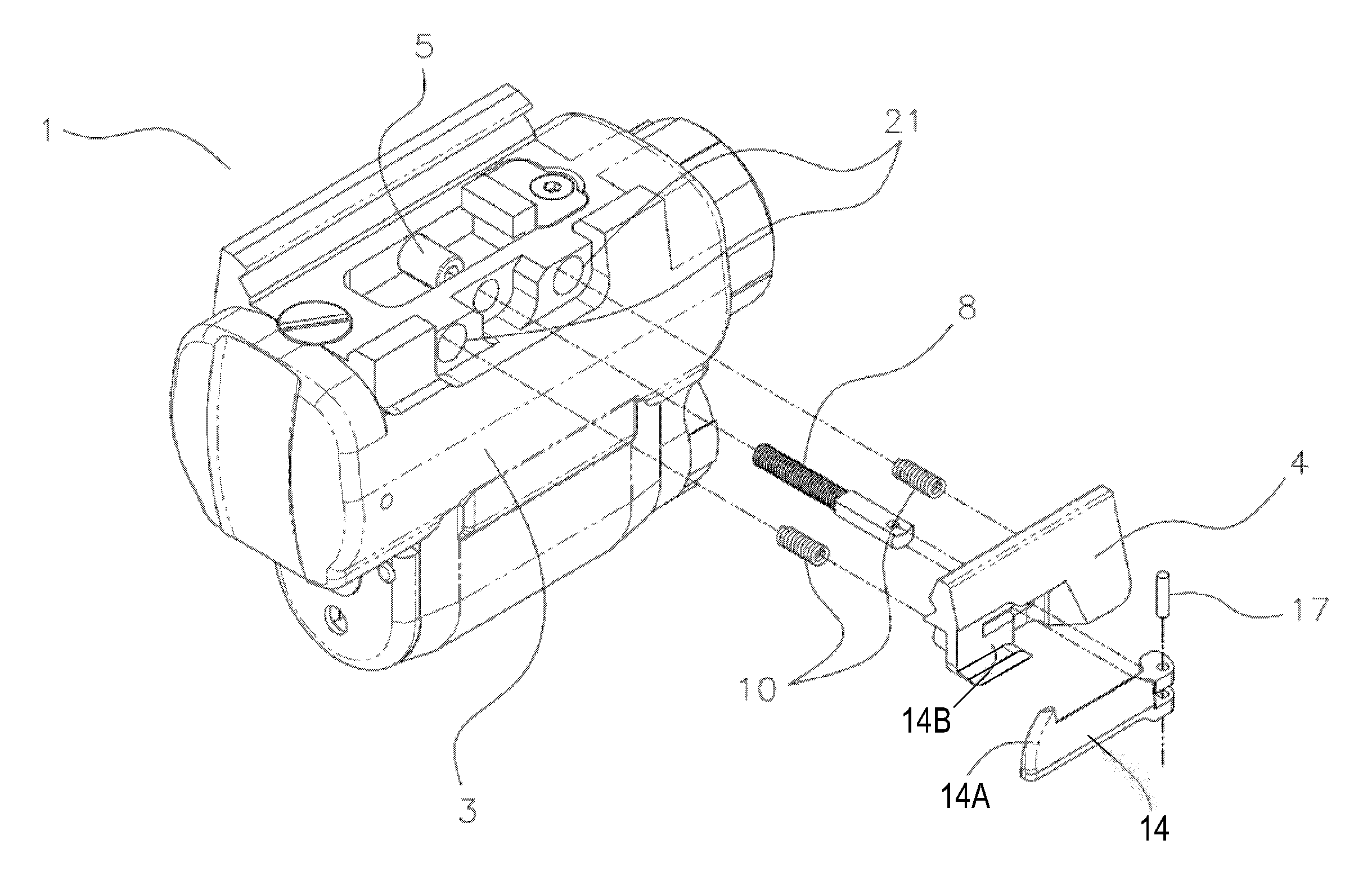
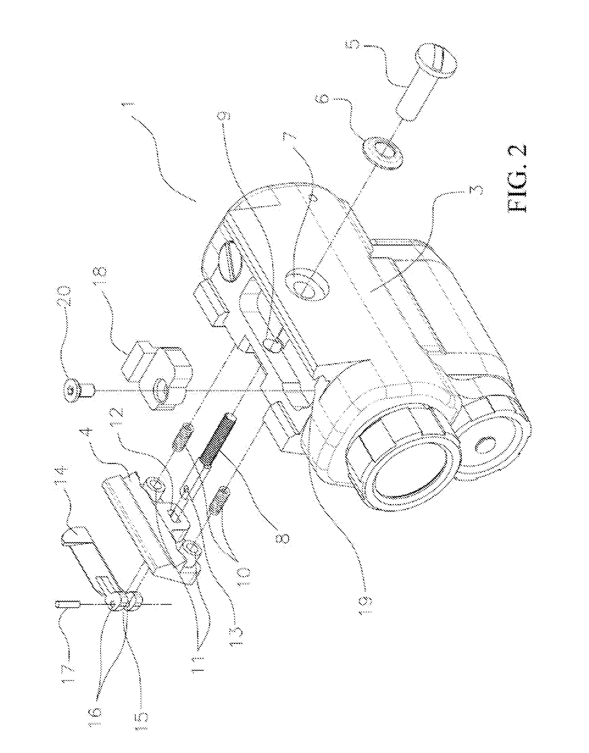
[0022]This invention allows for rapidly attaching or detaching a weapon-mountable lighting device to a weapon rail system, for example, a Picatinny 1913 or similar mounting schemes utilized with host weapon systems. As will be described below, the invention utilizes a cam lever to engage a floating rail clamp to apply pressure to a host weapon rail system. The floating rail is symmetrically biased in an open position to allow for rapid and solid attachment of a weapon-mountable lighting device to the rail of the host weapon, and also allows for quick detachment of the device.

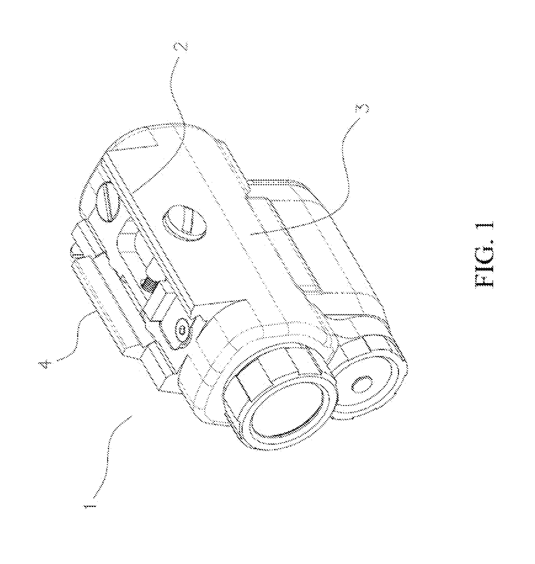
[0023]Referring to FIG. 1, a weapon-mountable lighting device is represented as being equipped with a rapid attachment / detachment mechanism 1 in accordance with an embodiment of the present invention. The lighting device may be, for example, a laser designator / illuminator commercially produced by Laser Genetics of America, LTD. The mechanism 1 comprises a rigid and fixed rail clamp 2 that is either integrated wi...


PUM


Abstract

A mechanism adapted for rapid attachment/detachment of a lighting device to a rail system of a host weapon system. The mechanism includes a body, a fixed rail clamp, and a floating rail clamp that is adjustably attached to the body in an opposing manner to the fixed rail clamp to provide a clamping effect therebetween. The floating rail clamp has a recess in a surface opposite the fixed rail clamp. A holding screw passes through a bore in the fixed rail clamp, and a clamp screw passes through a slot in the floating rail clamp and is threaded into one end of the holding screw. An oppositely-disposed end of the clamp screw protrudes within the recess of the floating rail clamp, and a cam arm has a first end pivotably coupled to the second end of the clamp screw and an oppositely-disposed distal end that protrudes from the recess.

Description

CROSS REFERENCE TO RELATED APPLICATIONS[0001]This application claims the benefit of U.S. Provisional Application No. 61 / 440,128, filed Feb. 7, 2011, the contents of which are incorporated herein by reference.BACKGROUND OF THE INVENTION:[0002]Existing weapon-mountable lighting devices use a variety of methods to secure the actual device to a host weapon system. The most common method involves clamping the device to a system such as the Picatinny 1913 mounting rail. A plethora of means of fixedly fastening these devices to a rail system exist and include, but are not limited to simple screw mechanisms that provide dual opposing lateral clamping force against a rail system, spring mechanisms that apply perpendicular force against a rail system, and even singular lateral clamping force against a rail system. Some of the commercially available systems' attachment means are not ruggedized, that is they do not maintain their position during normal use such as weapon transport or firing.[00...

Claims


Application Information

Patent Timeline
Patent Type & Authority Applications(United States)
IPC IPC(8): F41C27/00
CPCF41C27/00F41G11/003F41G1/35
Inventor RILEY, LOUIS F.CASAS, JUAN CARLOS
Owner CASAS JUAN CARLOS
Why Eureka
Try Eureka