Internal heat exchanger

Inactive Publication Date: 2012-08-09
HANON SYST
View PDF6 Cites 23 Cited by
  • Summary
  • Abstract
  • Description
  • Claims
  • Application Information

AI Technical Summary

Benefits of technology

[0007]In concordance and agreement with the present invention, an internal heat exchanger that is suitable for use in an air conditioning system of a motor vehicle, which is easily manufactured, easily conf

Problems solved by technology

Current internal heat exchangers used in the air conditioning systems are bulky, heavy, and/or expensive.
Further, t

Method used


Image

  • Internal heat exchanger
  • Internal heat exchanger
  • Internal heat exchanger

Examples


Embodiment Construction

[0023]The following detailed description and appended drawings describe and illustrate an exemplary embodiment of the invention. The description and drawings serve to enable one skilled in the art to make and use the invention, and are not intended to limit the scope of the invention in any manner.

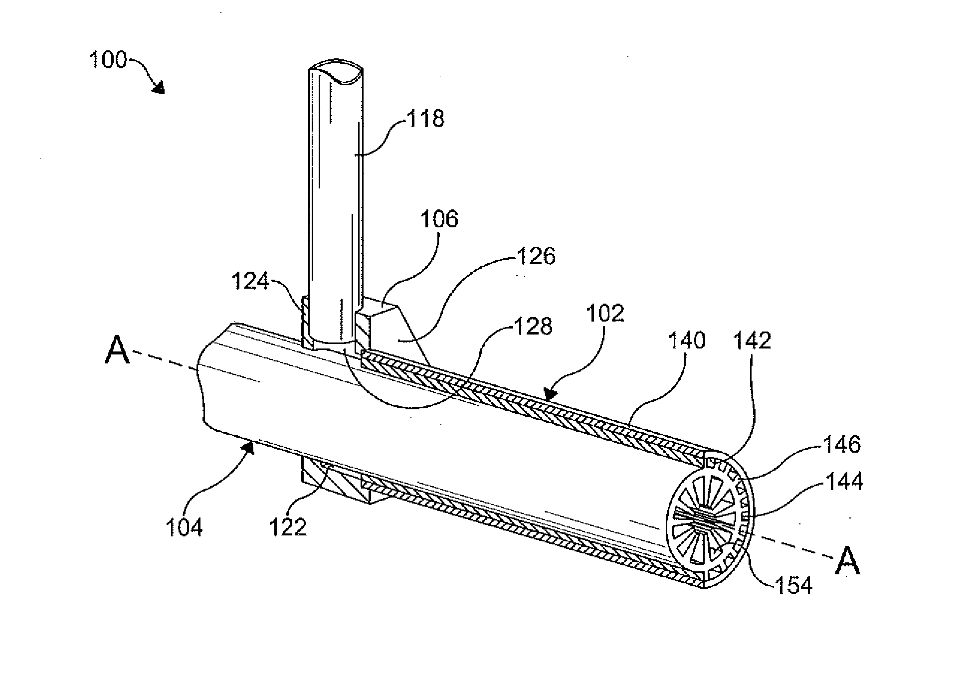
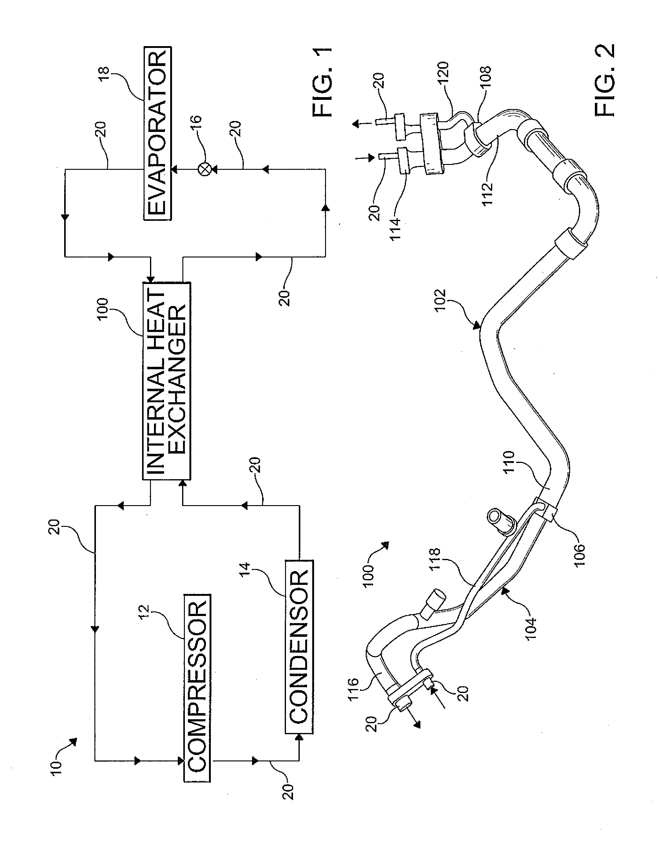
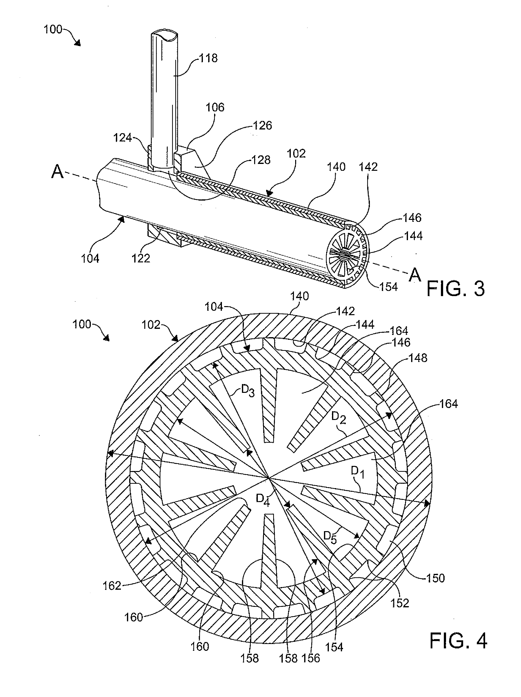
[0024]FIG. 1 is a schematic view of an air conditioning system 10 of a motor vehicle (not shown). The air conditioning system 10 includes a compressor 12, a condenser 14, an expansion device 16, and an evaporator 18 fluidly connected by conduits 20. The air conditioning system 10 further includes a counter flow or internal heat exchanger (IHX) 100 to increase a heat transfer capacity of the air conditioning system 10. It is understood that the IHX 100 is not limited to use in vehicle air conditioning systems 10, and can be employed in other non-automotive applications requiring a heat exchanger. It is further understood that the air conditioning system 10 can include other components neces...


PUM


Abstract

A heat exchanger includes an outer tube and an inner tube coaxially arranged within the outer tube. Both of the outer tube and the inner tube include a fluid channel formed therein. A first fluid flows through the fluid channel of the outer tube, and a second fluid, in heat exchange relationship with the first fluid, flows through the fluid channel of the inner tube. At least one heat conductive feature is formed between the outer tube and the inner tube, and on an inner surface of the inner tube to maximize a heat exchange between the fluids.

Description

FIELD OF THE INVENTION[0001]The present invention relates to a heat exchanger. More particularly, the invention is directed to an internal heat exchanger.BACKGROUND OF THE INVENTION[0002]A typical air conditioning system of a vehicle includes a compressor, a condenser, an expansion device, and an evaporator, all fluidly connected by refrigerant conduits. The refrigerant conduits are capable of conveying a flow of high and low pressure refrigerant. Common refrigerants used in the air conditioning systems are environmentally friendly refrigerants such as R-134a, for example, and low Global Warming Potential (GWP) refrigerants such as HFO-1234yf, for example. The compressor compresses and facilitates a transfer of the refrigerant throughout the system. The compressor includes a suction side and a discharge side. The suction side is referred to as the low pressure side and the discharge side is referred to as the high pressure side.[0003]Typically, the evaporator is disposed in a passen...

Claims


Application Information

Patent Timeline
IPC IPC(8): F28D7/10
CPCF25B40/00F28D7/106F28D7/103F28F1/422
Inventor SHELDON, DANIEL FRANKSCHROEDER, FRED GEORGMEYER, JOHN JOSEPHGOENKA, LAKHI NANDLALCEBE, PAVEL
Owner HANON SYST
Why Eureka
Try Eureka