Camera module with tolerance adjustment using embedded active optics

a technology of optical control and camera module, which is applied in the field of optical devices and assemblies, can solve the problems of insufficient optical and physical manufacturing tolerances to ensure the desired precision, and the overall device focusing power is changed, so as to achieve acceptable optical performance and shorten the overall lens design. the effect of the improvemen

Inactive Publication Date: 2012-08-09
POINT FINANCIAL
View PDF12 Cites 35 Cited by
  • Summary
  • Abstract
  • Description
  • Claims
  • Application Information

AI Technical Summary

Benefits of technology

[0006]In one particular embodiment of the present invention, a tunable liquid crystal optical device is used to compensate for variances in the focal length of the lens stack that occur due to manufacturing tolerances of a lens and imaging sensor assembly, such as the optical core of a fixed focus digital camera. Such an embodiment may include a fixed focus optical lens assembly, having one or more fixed focus optical lenses, through which an optical signal passes, as well as an electrically controllable active optical element, such as a TLCL. The active optical element changes its optical characteristics from a first state to a second state (e.g., from a first optical power to a second optical power) in response to an input electrical signal. This changes the influence that the element has on the optical signal, and may change the focusing power of the overall device. A mounting for the lens assembly, the image sensor and the active optical element supports these devices in their predetermined relative positions, but the optical and physical manufacturing tolerances are insufficient to ensure a desired precision of focus of an image on an image sensor of the device when the active optical element is at a nominal optical power. However, by controlling the active optical element, this tolerance inaccuracy can be compensated for to allow the image to be correctly focused on the image sensor. Thus, the task of adjusting mechanically the lens assembly with respect to the image sensor plane may be augmented by making focus adjustments using the active optical element.
[0009]The lens apparatus may have the active optical element positioned within a lens stack. In this configuration, by applying a required electrical signal to the active element, the optical properties of the lens assembly are modified without any mechanical movement. In case of a TLCL as the active optical element, the focal plane of the lens structure could be moved, thus creating a variable focus (e.g. auto focus) device. By including other features into the active element, this active element can also function as an aperture stop, shutter, IR cut filter or other mechanism in the lens stack, resulting in a possibly shorter and improved overall lens design.
[0010]A lens mounting structure having a barrel shape may also be used to enable easy assembly of the active element into the lens stack. In this embodiment, a lens barrel is split into two sections at the active optical element plane. Mechanical features on the fixed focus lens elements are used to establish assembly spacing and alignment. In this configuration, the active optical element is designed to be integrated into the stack without interfering with precise alignment and spacing of other optical elements within the stack. A special feature on the fixed elements is used to align and space these elements without interference from the active optical element. The active optical element may have a substantially planar shape and, in one embodiment, is roughly square. With such a square shape, extra space around the active optical element may be used to provide alignment and spacing, which is required in conventional fixed lens systems to achieve acceptable optical performance.

Problems solved by technology

This changes the influence that the element has on the optical signal, and may change the focusing power of the overall device.
A mounting for the lens assembly, the image sensor and the active optical element supports these devices in their predetermined relative positions, but the optical and physical manufacturing tolerances are insufficient to ensure a desired precision of focus of an image on an image sensor of the device when the active optical element is at a nominal optical power.

Method used


Image

  • Camera module with tolerance adjustment using embedded active optics
  • Camera module with tolerance adjustment using embedded active optics
  • Camera module with tolerance adjustment using embedded active optics

Examples


Embodiment Construction

[0035]The present invention is directed to an optical lens apparatus that uses fixed lenses in combination with an electrically controllable liquid crystal optical device. Depending on the specific configuration, the apparatus may be directed to one of several applications. In each of these embodiments, the apparatus uses the optical properties of the fixed lenses in combination with the electrically controlled optical properties of the liquid crystal device.

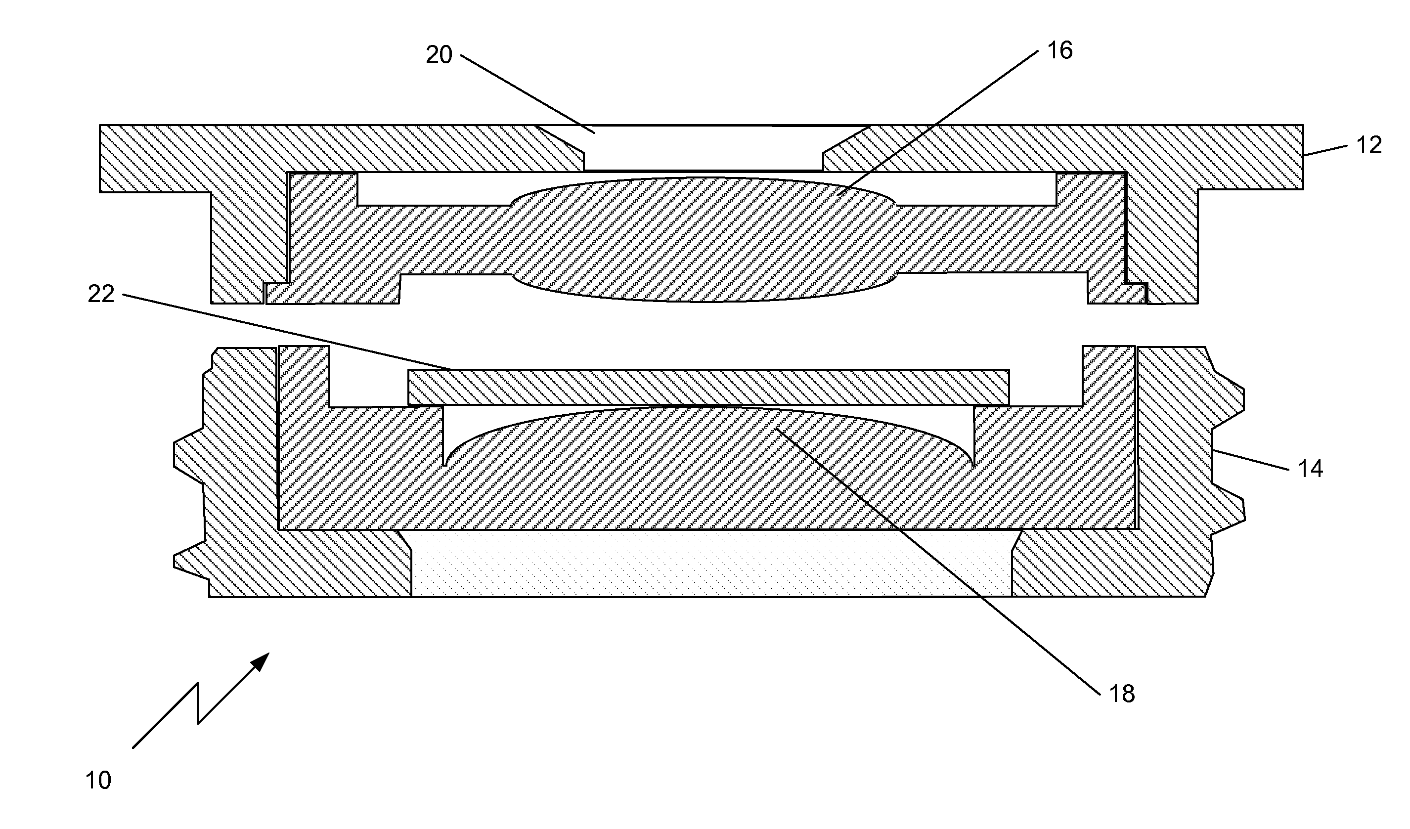
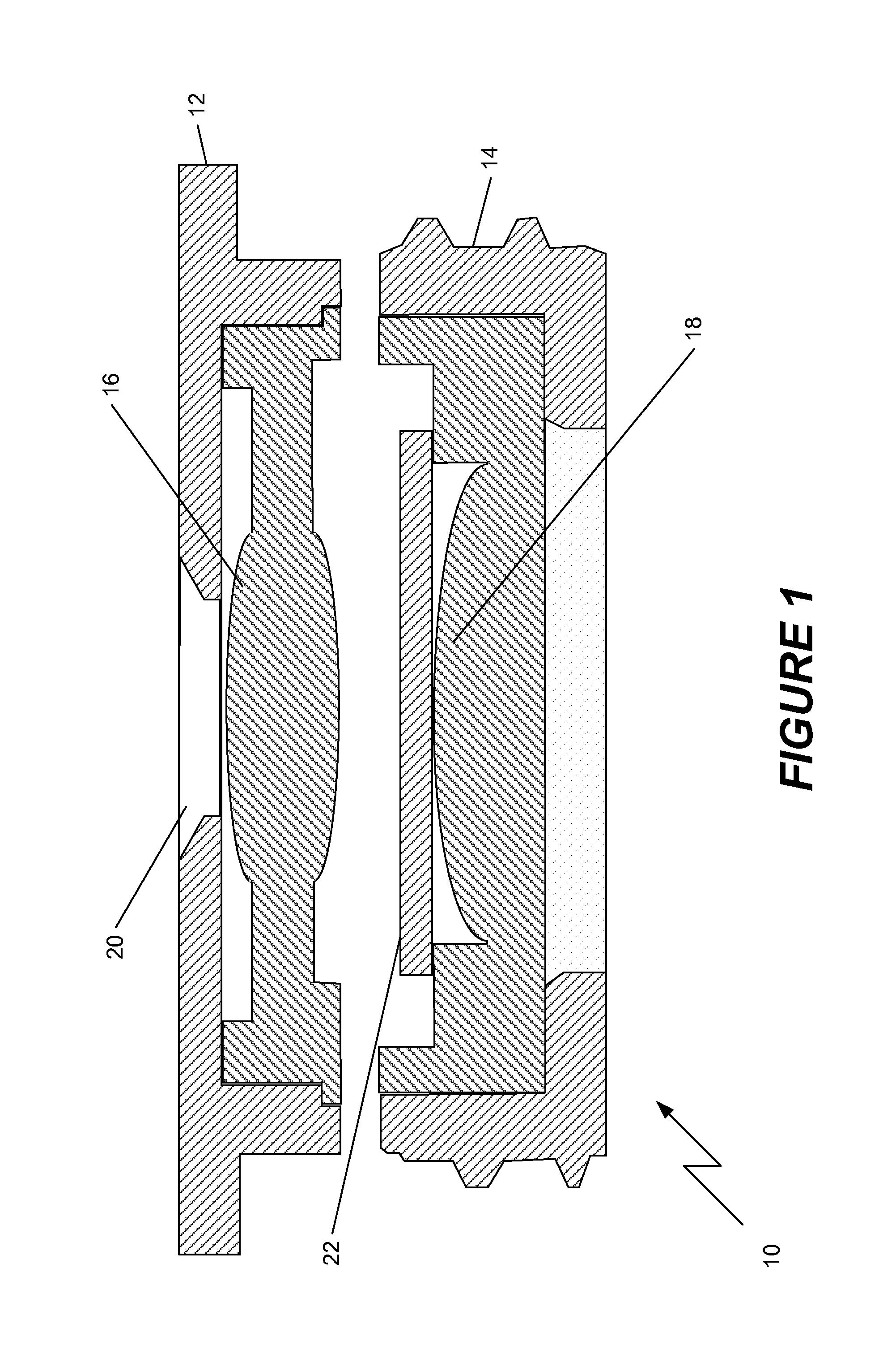
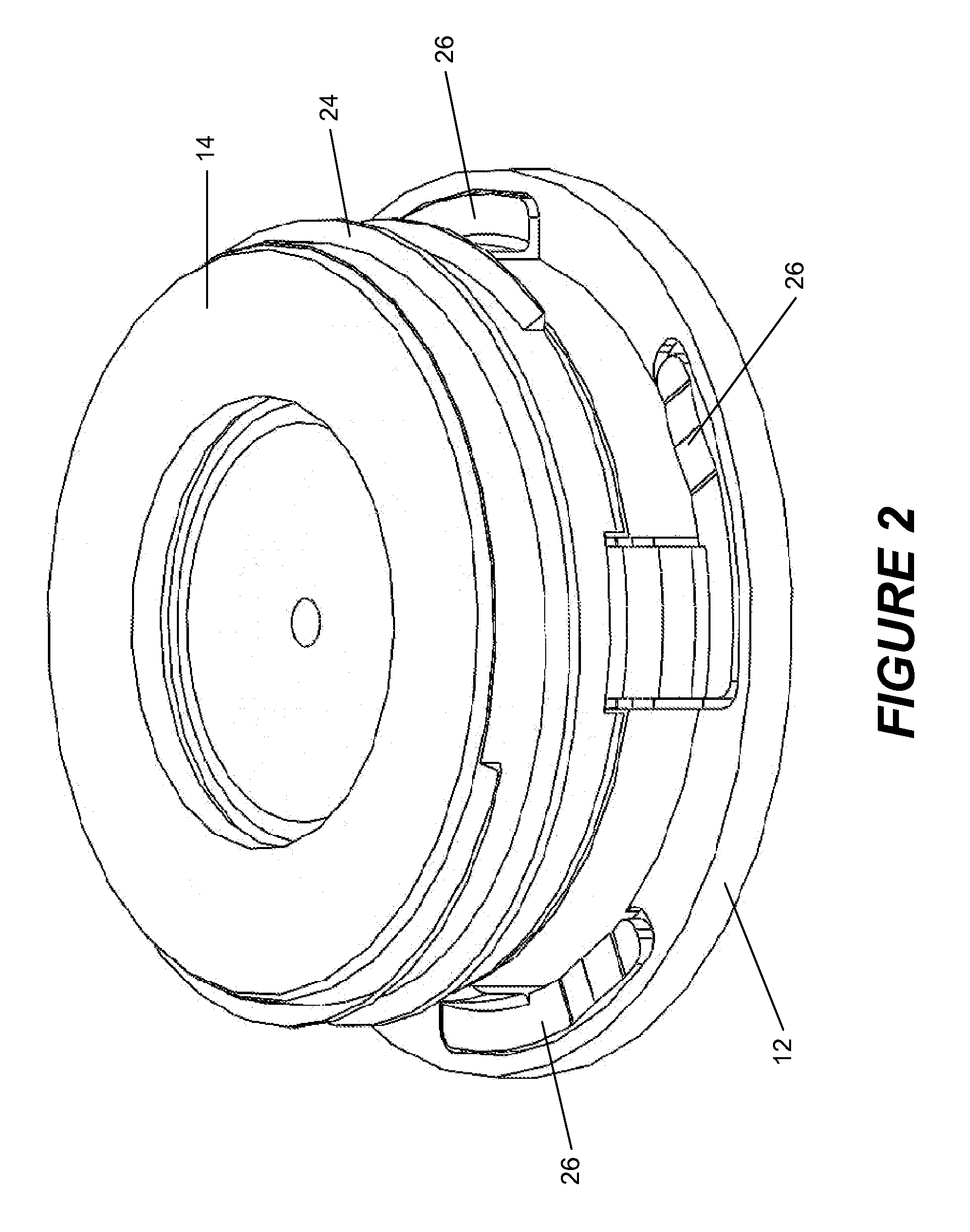
[0036]Shown in FIG. 1 is a schematic view of a first embodiment of the invention in which a variable focus lens 10 has a barrel structure consisting of two portions, an outer portion 12 and an inner portion 14. The lens may be used in a variety of different applications, including compact digital cameras, such as might be integrated into a portable telephone. Each of the two portions includes a fixed lens, lens 16 in the outer portion 12, and lens 18 in the inner portion 14. Each of the lenses in this embodiment are an integral ...


PUM

PropertyMeasurementUnit
optical poweraaaaaaaaaa
optical characteristicsaaaaaaaaaa

Abstract

A focus free camera module uses fixed lenses within a housing that are combined with an electrically controllable active optical element, such as a tunable liquid crystal lens. The fixed lenses provide a desired amount of optical power, but the manufacturing tolerances of the module are insufficient to ensure a proper focus of an image on an image sensor. The active optical element is therefore used to compensate for any variations in the optical power to achieve the desired focus. To ensure an effective compensation, the module may be constructed so that, when the variation in optical power due to manufacturing tolerances is at a maximum, the desired focus is achieved when the active optical element is at zero optical power. All other variations may then be compensated by adjusting the active optical element to increase its optical power.

Description

[0001]This application claims priority of U.S. provisional patent application 61 / 175,025 filed May 3, 2009.FIELD OF THE INVENTION[0002]This invention relates generally to optical devices and assemblies and, more specifically, to lenses having active optical control.BACKGROUND OF THE INVENTION[0003]Lens structures for optical devices such as cameras consist of multiple lens elements assembled in a single barrel or stacked in a wafer form, utilizing spacers, to create fixed focus lens assemblies. These lens structures have a fixed focal plane and are mechanically moved to focus on objects in varying distances to the camera system.[0004]Tunable liquid crystal lenses (TLCL) that have a flat layer construction are known in the art, as described in PCT patent application WO 2007 / 098602, published on Sep. 7, 2007, as well as in PCT patent application publication WO 2009 / 153764 published Dec. 23, 2009, the specifications of which are hereby incorporated by reference as if fully set forth he...

Claims


Application Information

Patent Timeline
Patent Type & Authority Applications(United States)
IPC IPC(8): G03B13/00H05K13/00H04N5/232
CPCH04N5/2254Y10T29/49002Y10T29/49004H04N5/2257H04N23/50H04N23/57
Inventor AFSHARI, BAHRAMTOOR, JOHNCLARK, PETER PHO, SAMUEL WENNYANN
Owner POINT FINANCIAL
Why Eureka
Try Eureka