Flow battery having a low resistance membrane

a flow battery and membrane technology, applied in the direction of secondary cell details, non-aqueous electrolyte cells, indirect fuel cells, etc., can solve the problem of reducing the overall energy efficiency of the flow battery system

Inactive Publication Date: 2012-08-09
UNITED TECH CORP
View PDF3 Cites 72 Cited by
  • Summary
  • Abstract
  • Description
  • Claims
  • Application Information

AI Technical Summary

Problems solved by technology

The mixing of the redox couple reactants can induce in a self-discharge reaction that can disadvantageously decrease the overall energy efficiency of the flow battery system, especially when the flow battery cells are operated at current densities less than 100 milliamps per square centimeter (mA / cm2), which is the typical current density operating range of conventional flow battery cells.

Method used


Image

  • Flow battery having a low resistance membrane
  • Flow battery having a low resistance membrane
  • Flow battery having a low resistance membrane

Examples


Embodiment Construction

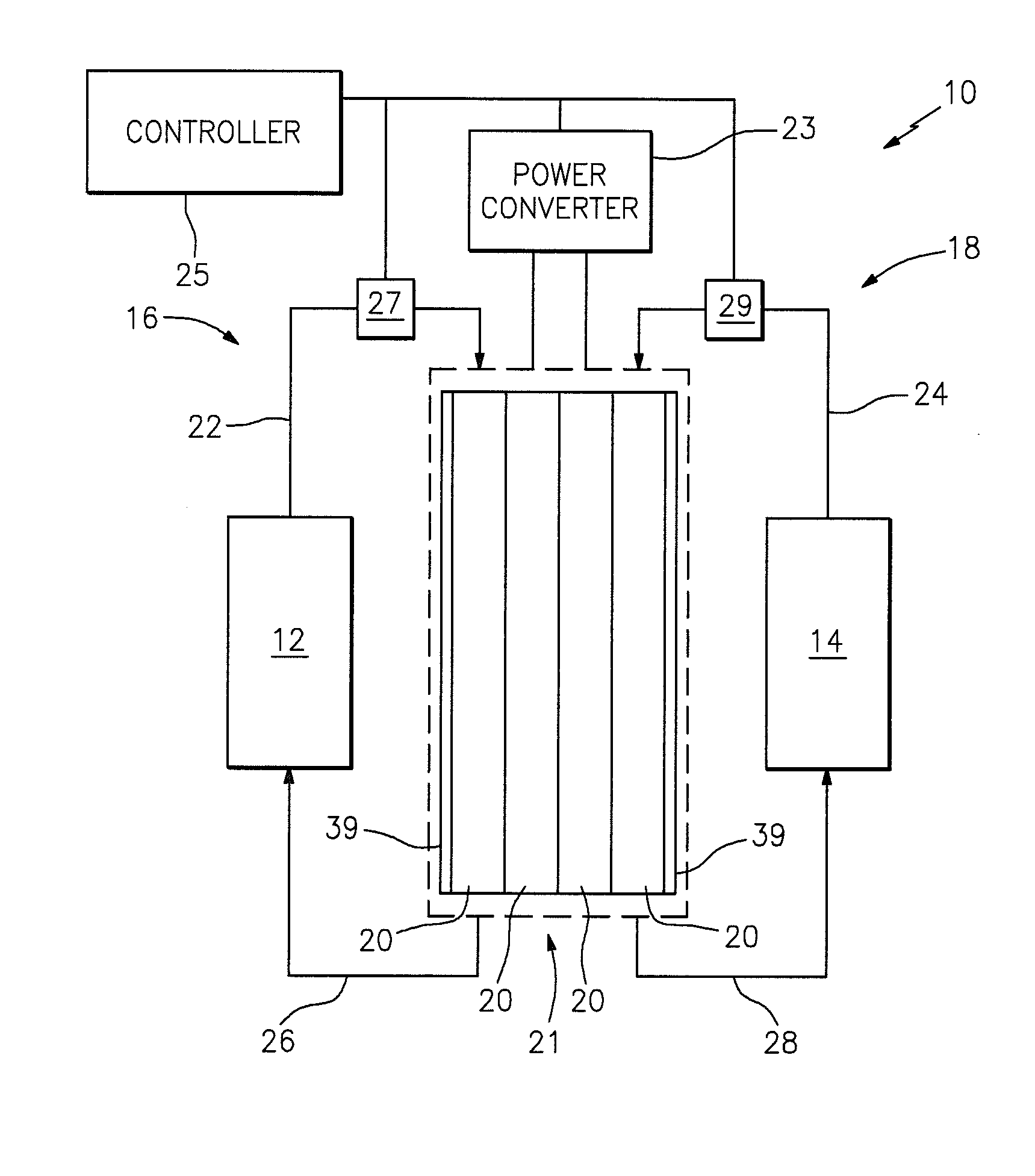
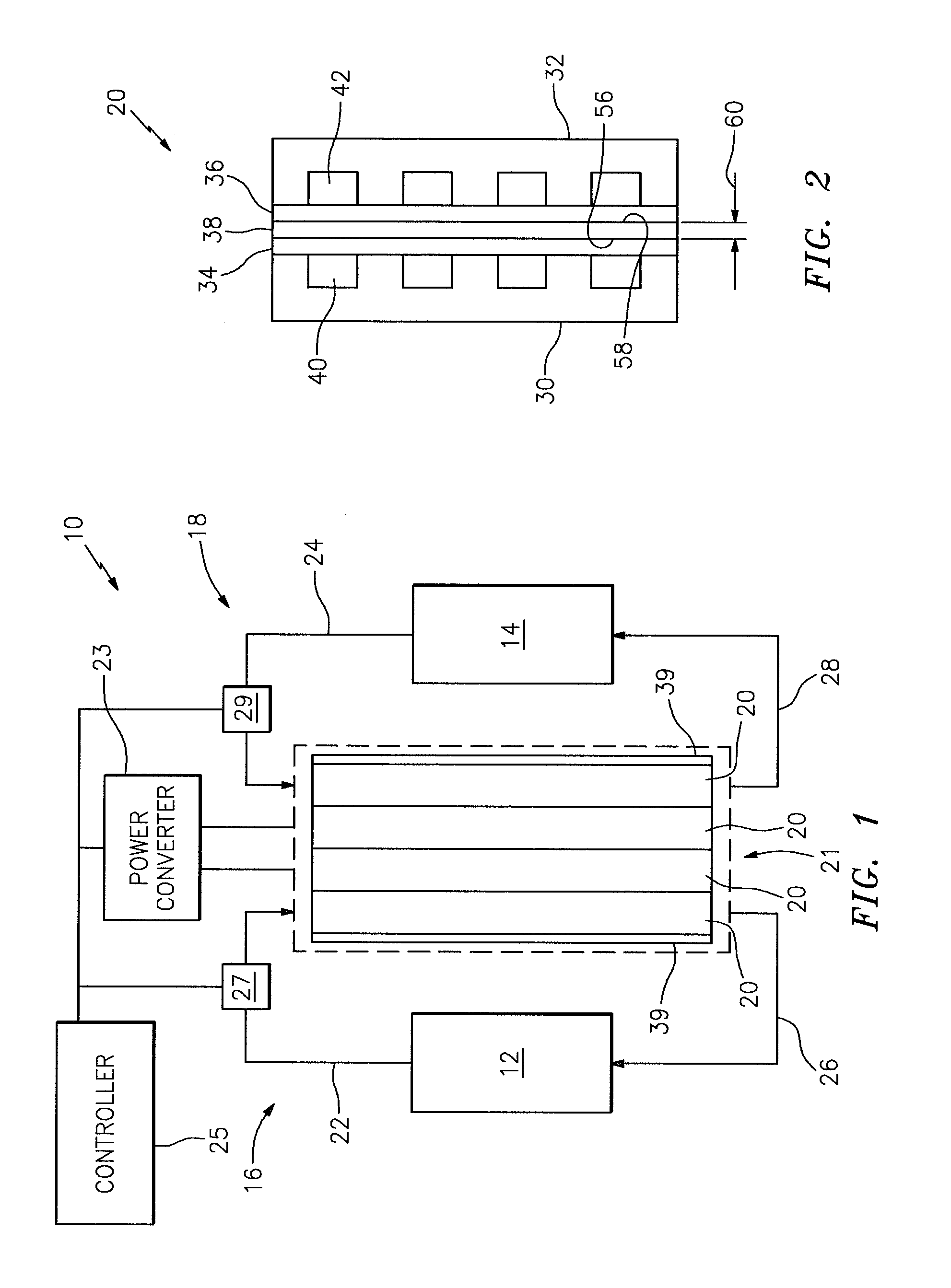
[0013]Referring to FIG. 1, a schematic diagram of a flow battery system 10 is shown. The flow battery system 10 is configured to selectively store and discharge electrical energy. By “store” it is meant that electrical energy is converted into a storable form that can later be converted back into electrical energy and discharged. During operation, for example, the flow battery system 10 can convert electrical energy generated by a renewable or non-renewable power system (not shown) into chemical energy, which is stored within a pair of first and second electrolyte solutions (e.g., anolyte and catholyte solutions). The flow battery system 10 can later convert the stored chemical energy back into electrical energy. Examples of suitable first and second electrolyte solutions include vanadium / vanadium electrolyte solutions, or any other pair of anolyte and catholyte solutions of substantially similar redox species. The pair of first and second electrolyte solutions, however, is not limi...


PUM

PropertyMeasurementUnit
thicknessaaaaaaaaaa
thickaaaaaaaaaa
current densitiesaaaaaaaaaa

Abstract

A flow battery includes a membrane having a thickness of less than approximately one hundred twenty five micrometers; and a solution having a reversible redox couple reactant, wherein the solution wets the membrane.

Description

CROSS-REFERENCE TO RELATED APPLICATIONS[0001]This application is related to PCT Application No. PCT / US09 / 68681 filed on Dec. 18, 2009 and U.S. patent application Ser. No. 13 / 022,285 filed on Feb. 7, 2011, each of which is incorporated by reference in its entirety.BACKGROUND[0002]1. Technical Field[0003]This disclosure relates generally to a flow battery system and, more particularly, to a flow battery having a low resistance membrane.[0004]2. Background Information[0005]A typical flow battery system includes a stack of flow battery cells, each having an ion-exchange membrane disposed between negative and positive electrodes. During operation, a catholyte solution flows through the positive electrode, and an anolyte solution flows through the negative electrode. The catholyte and anolyte solutions each electrochemically react in a reversible reduction-oxidation (“redox”) reaction. Ionic species are transported across the ion-exchange membrane during the reactions, and electrons are t...

Claims


Application Information

Patent Timeline
Patent Type & Authority Applications(United States)
IPC IPC(8): H01M10/02H01M4/02
CPCH01M8/188H01M8/20Y02E60/528H01M2300/0091H01M2300/0094H01M2300/0025Y02E60/50H01M8/10H01M8/18
Inventor PERRY, MICHAEL L.PANDY, ARUNZAFFOU, RACHIDWALKER, CRAIG R.
Owner UNITED TECH CORP
Why Eureka
Try Eureka