Method and system for software behaviour management

a software behaviour and behavior technology, applied in the field of software behaviour management, can solve the problems of dramatic variations in available resources, and the prediction of the exact behavior of an application in the customer production environment from the results of functional test cases identified in the design phase,

Inactive Publication Date: 2012-08-09
IBM CORP
View PDF14 Cites 35 Cited by
  • Summary
  • Abstract
  • Description
  • Claims
  • Application Information

AI Technical Summary

Benefits of technology

[0004]As discussed, prior art testing techniques concentrate on identifying minimum system requirement is a static manner. It is an aim of the present...

Problems solved by technology

The prediction of the exact behavior of an application in customer production environments from the results of functional test (FVT) cases identified in the design phase is extremely challenging, even if these are integrated with additional tests (capacity planning, system test) commonly adopted in software development laboratories.
Most likely such test cases identify meaningful tests from the functional point of view but they are executed in operating conditions that are unlikely to match...

Method used


Image

  • Method and system for software behaviour management
  • Method and system for software behaviour management
  • Method and system for software behaviour management

Examples


first embodiment

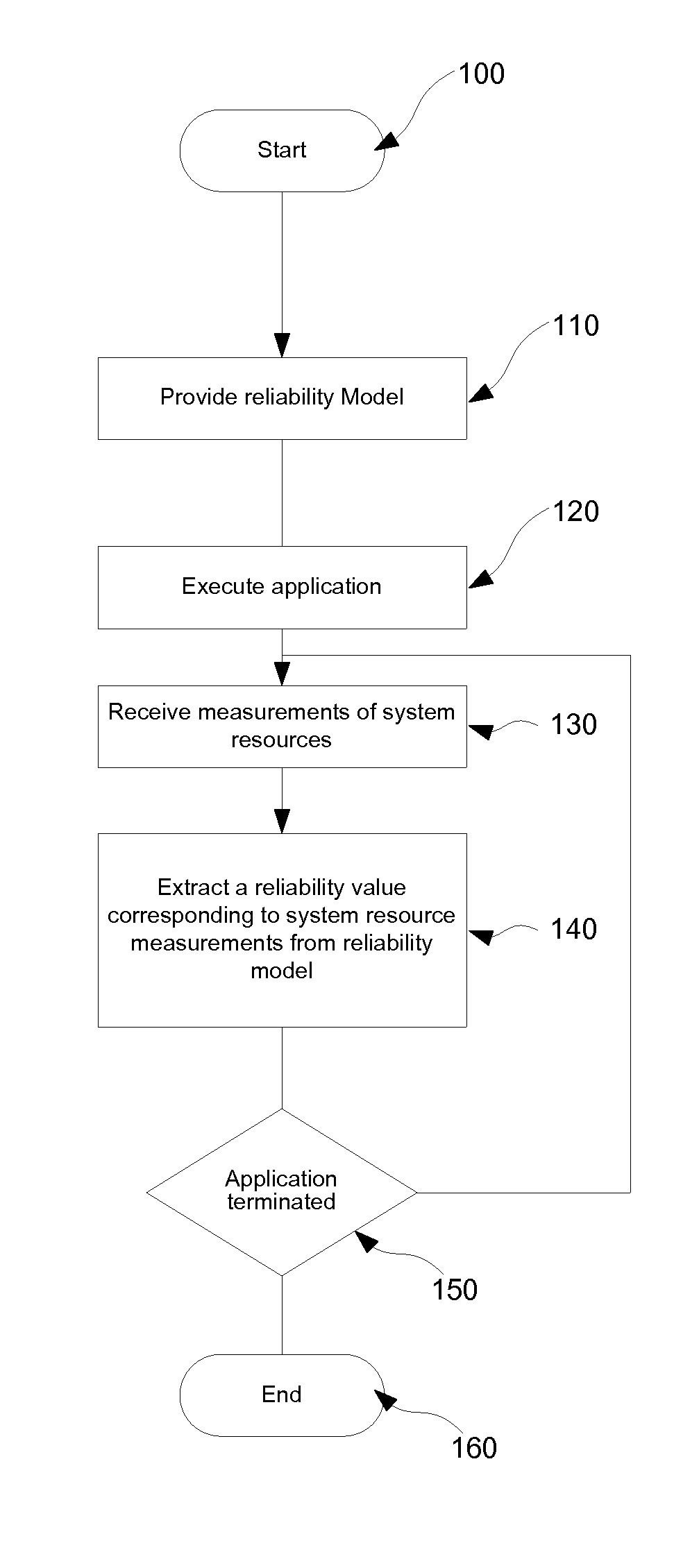
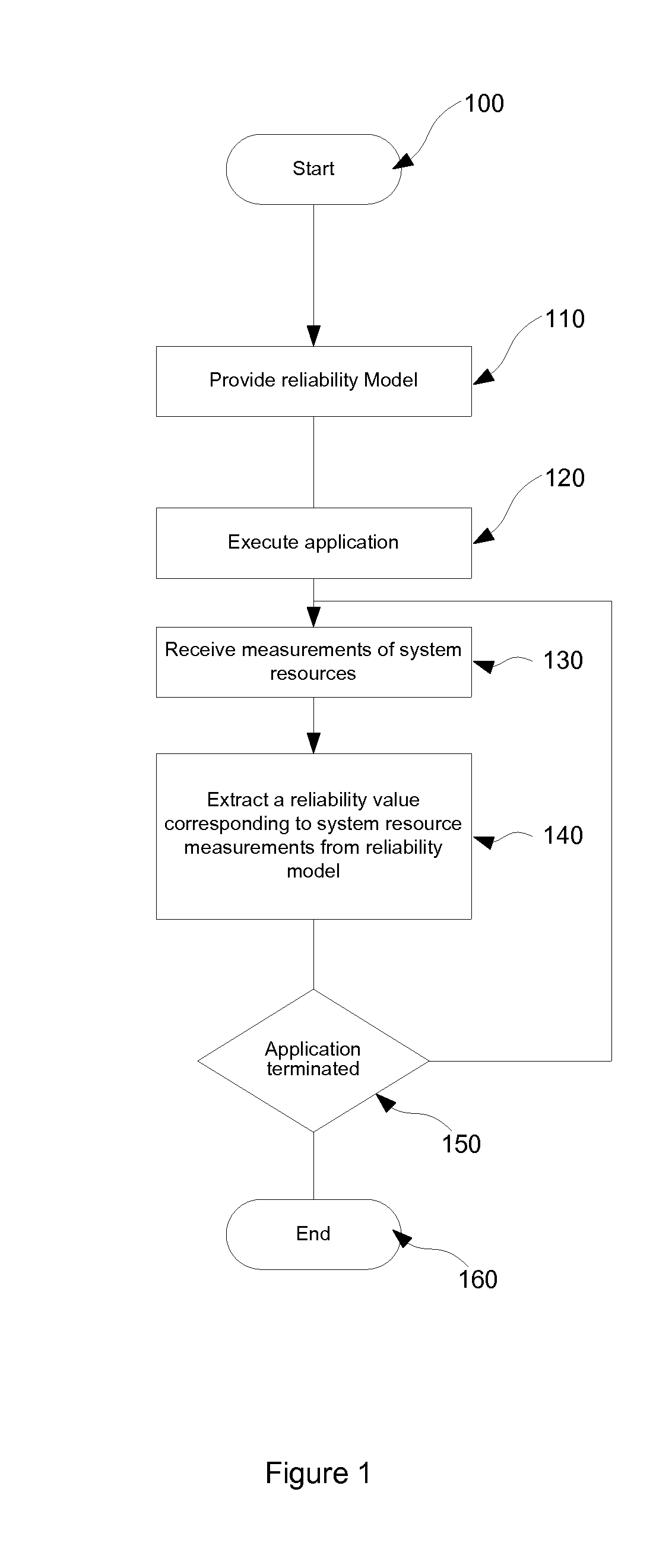
[0015]FIG. 1 shows the steps of the present invention. As shown, the process starts at step 100, and proceeds to step 110 at which a performance model for example as described in further detail hereafter is provided. At step 120 the application to which the performance model relates is executed, and at step 130 measurements the system resources used to define the model are received, for example from the operating system or other monitoring software or hardware. At step 140 the measurements are used to extract a performance value from the performance model corresponding to said measurements. At step 150 it is determined whether the application has terminated, in which case the process terminates at step 160, or otherwise the process returns to step 130, so that the process continues to monitor the performance level of the software as a function of monitored system resource availability for as long as the application is operational. Accordingly, there is provided a method of optimisin...

second embodiment

[0030]FIG. 4 shows the steps of the present invention. The process of FIG. 4 is the same as that as FIG. 3, but details certain exemplary sub-steps of the step 110 of providing a performance model. More specifically, FIG. 4 shows one possible method of creating such a performance model. As shown, the process defined in the substep 110 starts at step 411, whereby the resources of a test system are configured for the purposes of a test execution. As discussed above, this may be implemented in many ways depending on the nature of the test system itself, for example by suitably configuring a virtual machine, application server etc. The process next proceeds to step 413 during which the application is monitored and any errors recorded. Once the application has been run to termination, or through a predefined test sequences, or for a predefined period of time, the process proceeds to step 415, at which it is considered whether the application has been executed under each of the different ...

third embodiment

[0048]FIG. 5 shows the steps of the present invention. The process of FIG. 5 is the same as that as FIG. 3, but details certain further steps between steps 140 and 150. More specifically, FIG. 5 shows one way of using the performance value extracted from the performance model at step 140. As shown, rather than proceeding directly to step 150 after step 140 the process proceeds to step 541, at which it is determined whether the performance value extracted at step 140 falls below a predetermined threshold or not. In accordance with present embodiment, this predetermined threshold represents an acceptable performance level. This threshold may be a value specifically associated with the application, a particular user account, a particular machine, the time of day at which the application is executed, etc. There may be defined a hierarchy of applications, whereby the threshold for a particular application is defined by its position in that hierarchy, such that more important or urgent ap...


PUM


Abstract

A performance or reliability model representing the behaviour of an application under different system resource conditions is provided. This model may take the form of one or more sparse matrix providing a reliability or performance values for different combinations of conditions. This model is distributed to a user of the application, and is consulted during execution of the application with reference to system resource information provided by the operating system or other monitoring software so as to provide an indication of the expected performance of the application under present operating conditions. This indication may be notified to a user, for example in a case where the indication falls outside predetermined bounds of satisfactory operation. The system may also attempt to renegotiate attributed system resources to as to improve performance.

Description

FIELD OF THE INVENTION[0001]The present invention relates to a method and system for managing the behaviour of software as a function of the resources available to that piece of software. Background of the invention The prediction of the exact behavior of an application in customer production environments from the results of functional test (FVT) cases identified in the design phase is extremely challenging, even if these are integrated with additional tests (capacity planning, system test) commonly adopted in software development laboratories. Most likely such test cases identify meaningful tests from the functional point of view but they are executed in operating conditions that are unlikely to match the exact customer execution environment in the production phase.[0002]A widely used approach for large applications to address this problem is so called “capacity planning” or “performance load” testing, in which some specific (example precise hardware resources requirements) and rel...

Claims


Application Information

Patent Timeline
IPC IPC(8): G06F9/45G06F9/455
CPCG06F9/455G06F9/505G06F11/3461G06F11/3442G06F11/3447G06F11/008G06F2201/865
Inventor GANGEMI, ROSARIOSCIACCA, VINCENZOVILLANI, MASSIMO
Owner IBM CORP
Why Eureka
Try Eureka