Controlled-gradient, accelerated-vapor-recompression apparatus and method

a vapor recompression apparatus and acceleration technology, applied in the field of heat transfer, can solve the problems of reducing the efficiency of evaporator recompression, so as to achieve the effect of reducing the accretion of compounds

Active Publication Date: 2012-08-16
PURESTREAM SERVICES
View PDF16 Cites 0 Cited by
  • Summary
  • Abstract
  • Description
  • Claims
  • Application Information

AI Technical Summary

Benefits of technology

[0024]The material may selected to be chemically inert and non-reactive with respect to the medium. It may also be selected to minimize accretion of compounds generated in the medium.
[0025]A method for improving a process for vapor recompression, may include selecting a process comprising a plurality of operations combinable as

Problems solved by technology

The chemical constitution of dissolved materials, especially dissolved solids, as well as various ions and the like take a toll in energy and damage to the processing equipment for energy exchange.
For example, oil production results in pumping considerable water to the surface.
Therefore the water cannot be released into other water flows without treatment.
Meanwhile, disposal by hauling, followed by r

Method used


Image

  • Controlled-gradient, accelerated-vapor-recompression apparatus and method
  • Controlled-gradient, accelerated-vapor-recompression apparatus and method
  • Controlled-gradient, accelerated-vapor-recompression apparatus and method

Examples


Embodiment Construction

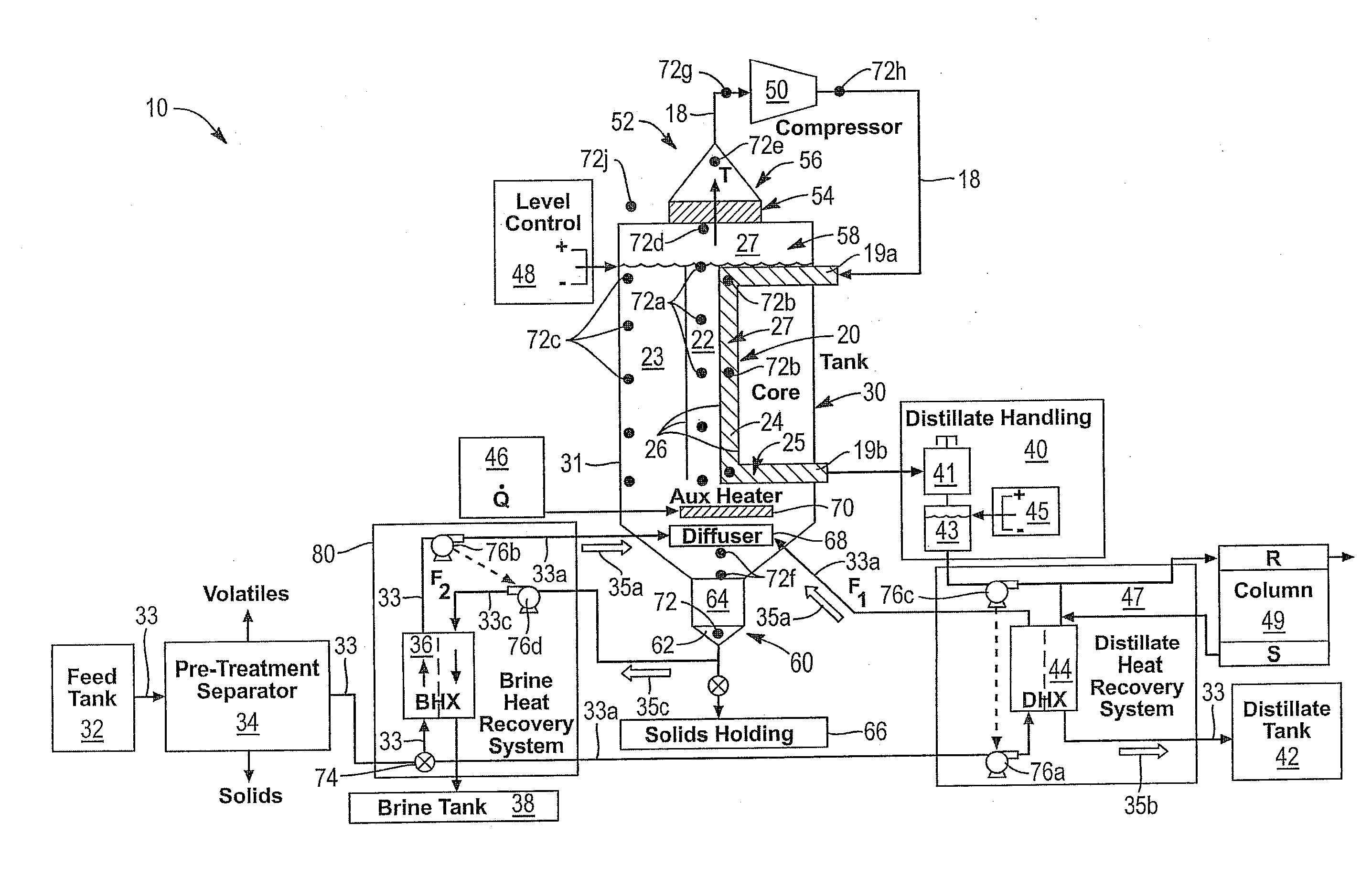
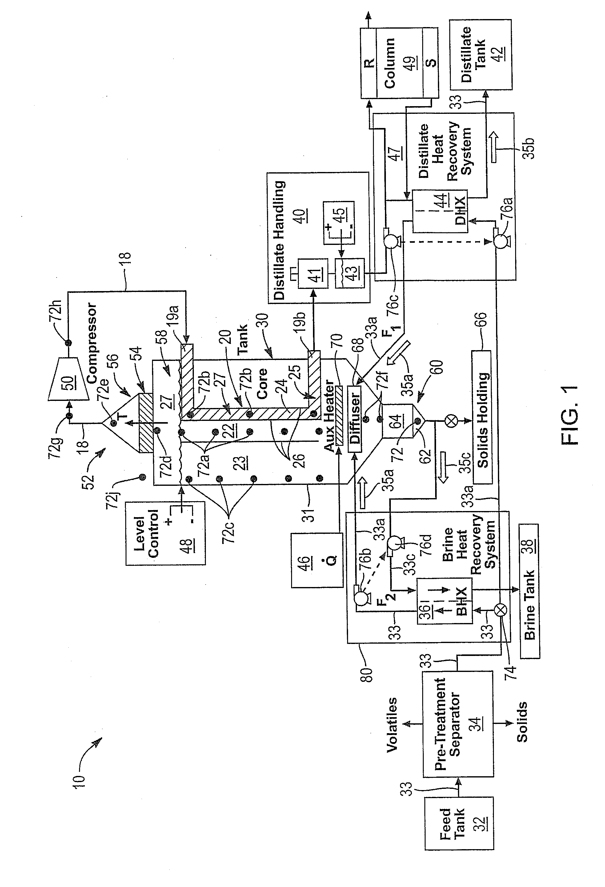
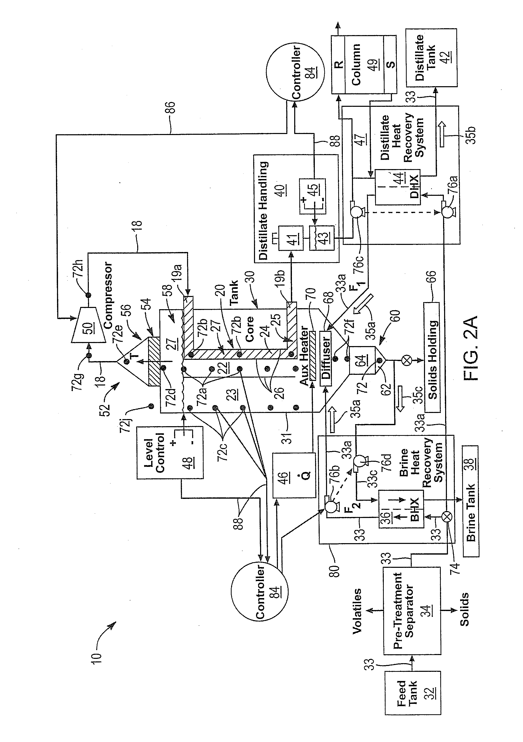
[0050]It will be readily understood that the components of the present invention, as generally described and illustrated in the drawings herein, could be arranged and designed in a wide variety of different configurations. Thus, the following more detailed description of the embodiments of the system and method of the present invention, as represented in the drawings, is not intended to limit the scope of the invention, but is merely representative of various embodiments of the invention. The illustrated embodiments of the invention will be best understood by reference to the drawings, wherein like parts are designated by like numerals throughout.

[0051]As used herein, terms are to be understood and interpreted broadly. However, alternative, specific terms may be used by way of example, but are to be interpreted as meaning the broader terms. For example a solvent or liquid is exemplified by water, but may be interpreted as any solvent, liquid, material, medium, carrier, or the like. ...


PUM

PropertyMeasurementUnit
Temperatureaaaaaaaaaa
Timeaaaaaaaaaa
Pressureaaaaaaaaaa

Abstract

An accelerated vapor recompression apparatus 10 converts incoming flow 35a to a concentrate 35c by developing a concentration profile 146 within a tank 30 holding a liquid 23 containing dissolved solids. The resulting curve 160 of saturation temperature of the stratified liquid 23 (such as a brine 23 or other material 23) moves away from the curve 162 corresponding to fully mixed conditions. The shift 174, 180 in saturation temperature results in increased boiling without increased energy from a heater 70 or compressor 50. A method 90, 200 of control of the system provides interventions 203,204, 205, 206 at different levels 92, 94, 96, 98 of control, ranging from mass flows 35 to work of a compressor 50, heat from a heater 70, and a predictive processing 215 of feedback 217 for controlling commands 216 algorithmically.

Description

RELATED APPLICATIONS[0001]This application claims the benefit of co-pending U.S. Provisional Patent Application Ser. No. 61 / 443,245 filed Feb. 15, 2011 and entitled CONTROLLED GRADIENT VAPOR RECOMPRESSION SYSTEM, which is incorporated herein by reference in its entirety.BACKGROUND[0002]1. The Field of the Invention This invention relates to heat transfer and, more particularly, to novel systems and methods for vapor recompression.[0003]2. The Background Art[0004]Heat recovery is the basis of electrical co-generation plants. Likewise many food and beverage processes require heat recovery for economy. Meanwhile, desalination plants, sugar processing, distillation systems, and the like rely on recovery of latent heat in order to minimize net energy requirements. Heat may be recovered by reheating, pre-heating, or otherwise exchanging heat from an exit flow into and incoming flow through a system of heat exchangers.[0005]Vapor recompression is used in various forms as one method for hea...

Claims


Application Information

Patent Timeline
IPC IPC(8): B01D1/28B01D3/42
CPCB01D1/0082B01D1/2856B01D1/30F28D21/0001B01D3/02B01D5/006B01D1/28B01D3/007B01D5/0039B01D3/42
Inventor BATTY, J. CLAIRRICHARDSON, NEIL W.BELL, DAVID A.MILLER, CHRISTOPHER M.
Owner PURESTREAM SERVICES
Why Eureka
Try Eureka