Compression-ignition internal combustion engine

a compression ignition and internal combustion engine technology, applied in the direction of machines/engines, electrical control, mechanical equipment, etc., can solve the problems of increased exhaust gas emissions and unstable cavitation flow, and achieve the effect of reducing exhaust gas emissions

Inactive Publication Date: 2006-11-02
DAIMLER AG
View PDF9 Cites 11 Cited by
  • Summary
  • Abstract
  • Description
  • Claims
  • Application Information

AI Technical Summary

Benefits of technology

[0007] Accordingly, a controlled injection of the fuel for varying the jet length in the combustion space can be carried out as a function of the piston position in the cylinder, with the result that the intermixing of the injected fuel with the combustion space air, particularly during preinjection and postinjection, takes place before the cylinder wall is reached. A wetting of the cylinder wall with fuel can thereby largely be avoided.
[0008] According to a refinement of the invention, the rows of holes of the injection nozzle have different injection-hole cone angles. The fuel can thereby, in particular, be introduced into the combustion space at a steeper injection angle during a preinjection or during a postinjection than during the main injection. The jet length in the combustion space can thus be adapted as a function of the distance between the injection nozzle and the piston, so that a variation in the jet length in order to optimize the mixture formation is thereby ensured or made possible.
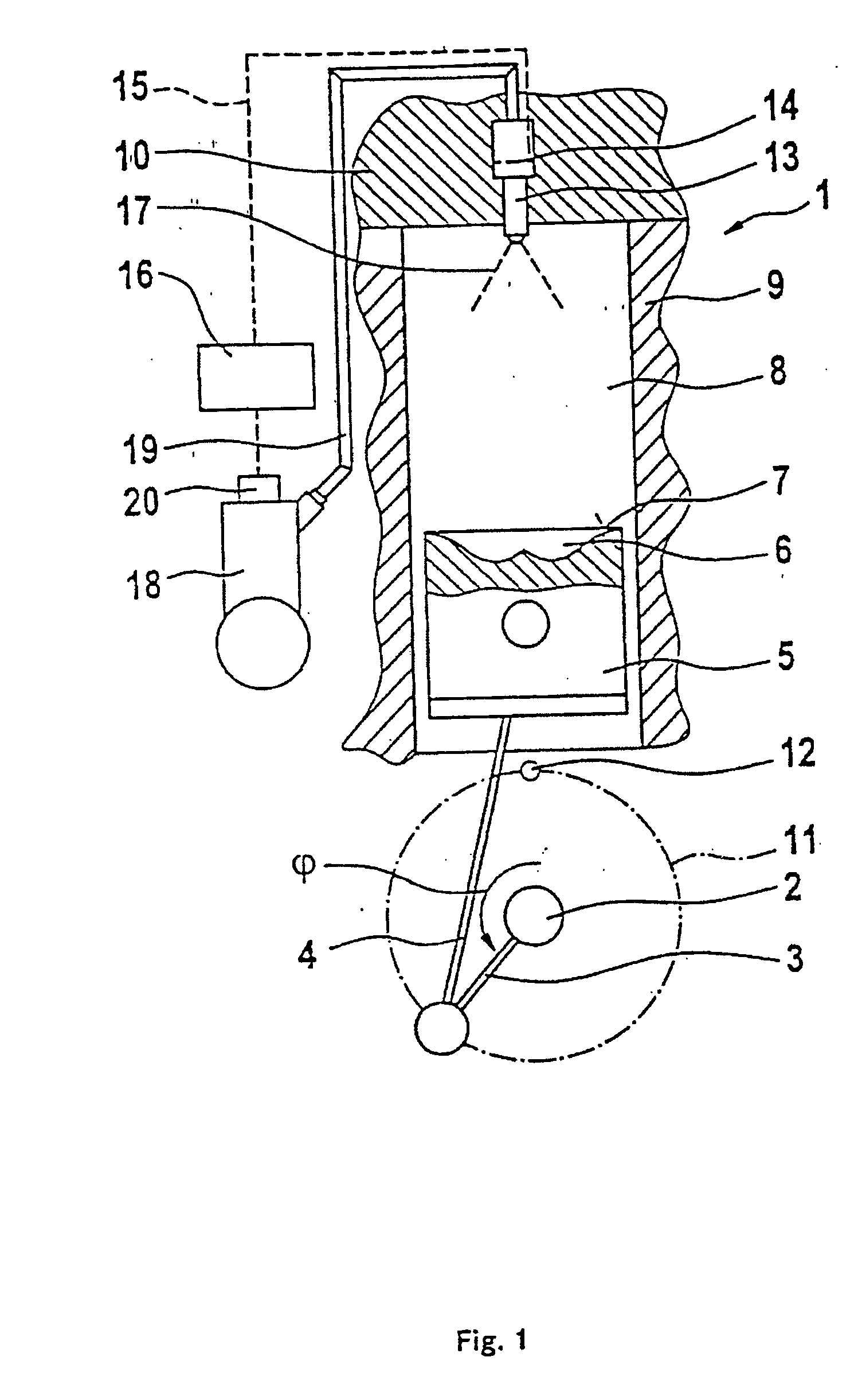
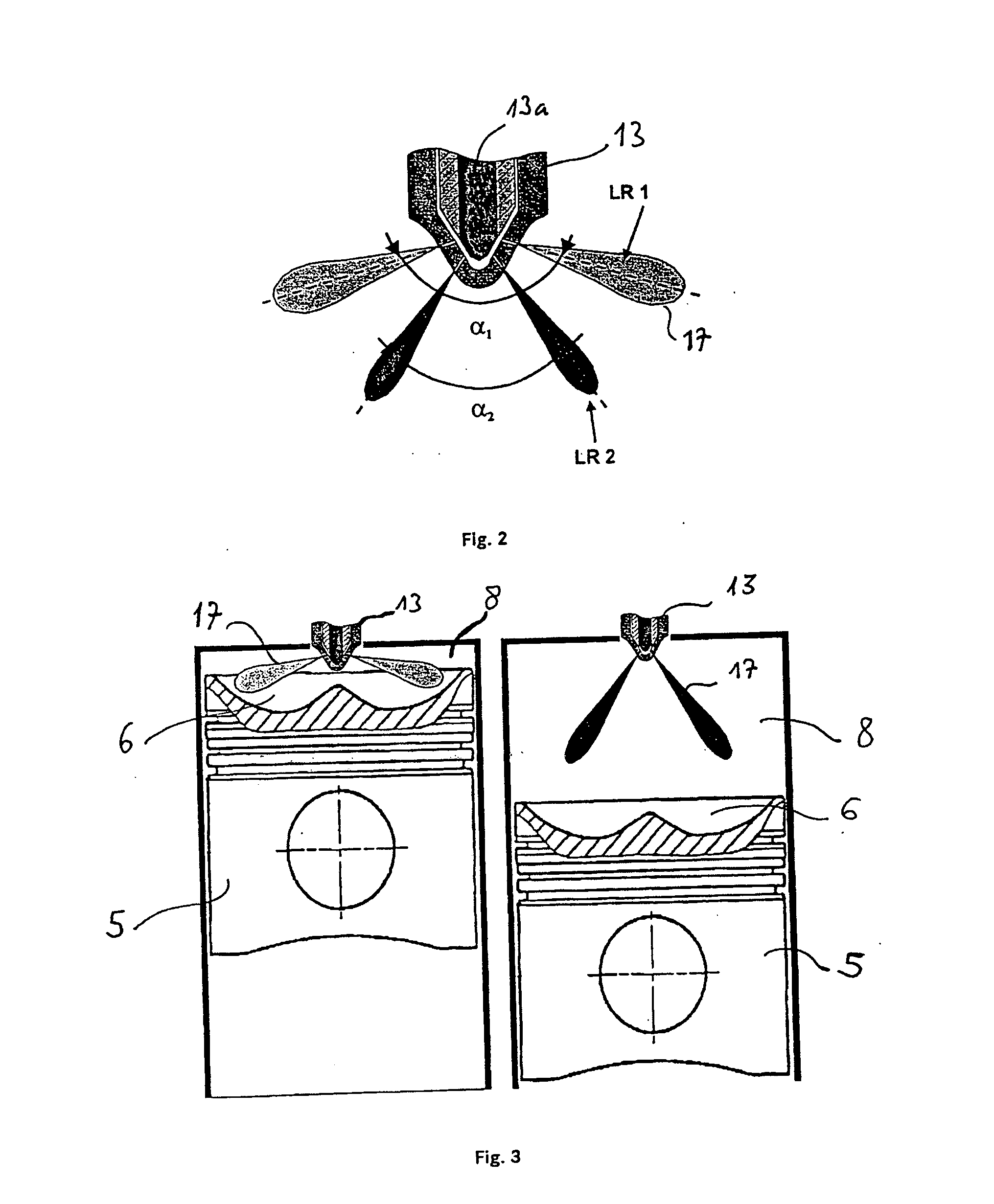
[0009] In a further refinement of the invention, a first row of holes of the injection nozzle is activated during main injection and a second row of holes is activated during preinjection and / or postinjection, the injection-hole cone angle of the first row of holes being higher than the injection-hole cone angle of the second row of holes. In this case, during the main injection, the fuel is injected around a top dead center through the first row of holes at a flat injection-hole cone angle, preferably of between 140° and 160°. By contrast, in the event of early and / or late fuel injection, the fuel is injected into the combustion space at a steep injection cone angle, for example of between 60° and 160°, through the second row of holes arranged preferably below the first row of holes. This makes it possible to have an optimum jet length in the combustion space during an injection operation. According to the invention, depending on the operating point, an injection operation comprises a main injection and, as required, a preinjection and / or postinjection.
[0011] In a further refinement of the invention, an operating stroke of the nozzle needle of the injection nozzle can be set in such a way that an unstable cavitating flow is formed in the injection bores of the injection nozzle. Preferably, during the preinjection and / or postinjection, the fuel is injected intermittently in the form of small part quantities. Accordingly, owing to the variable setting of the operating stroke of the nozzle needle of the injection nozzle, in the case of each preinjection or postinjection part quantity injected into the combustion space, the atomization of the respective fuel jet in the combustion space can be reinforced, so that a wall accretion of fuel in the cylinder, which, for example, rises continuously in the case of a lower gas pressure and lower temperature in the cylinder, is minimized. Thus, according to the invention, the range of each part quantity up to a combustion space wall is limited and an intensified break-up and evaporation of the injection jet or of the part quantity, particularly with an increasingly later start of injection, are achieved.
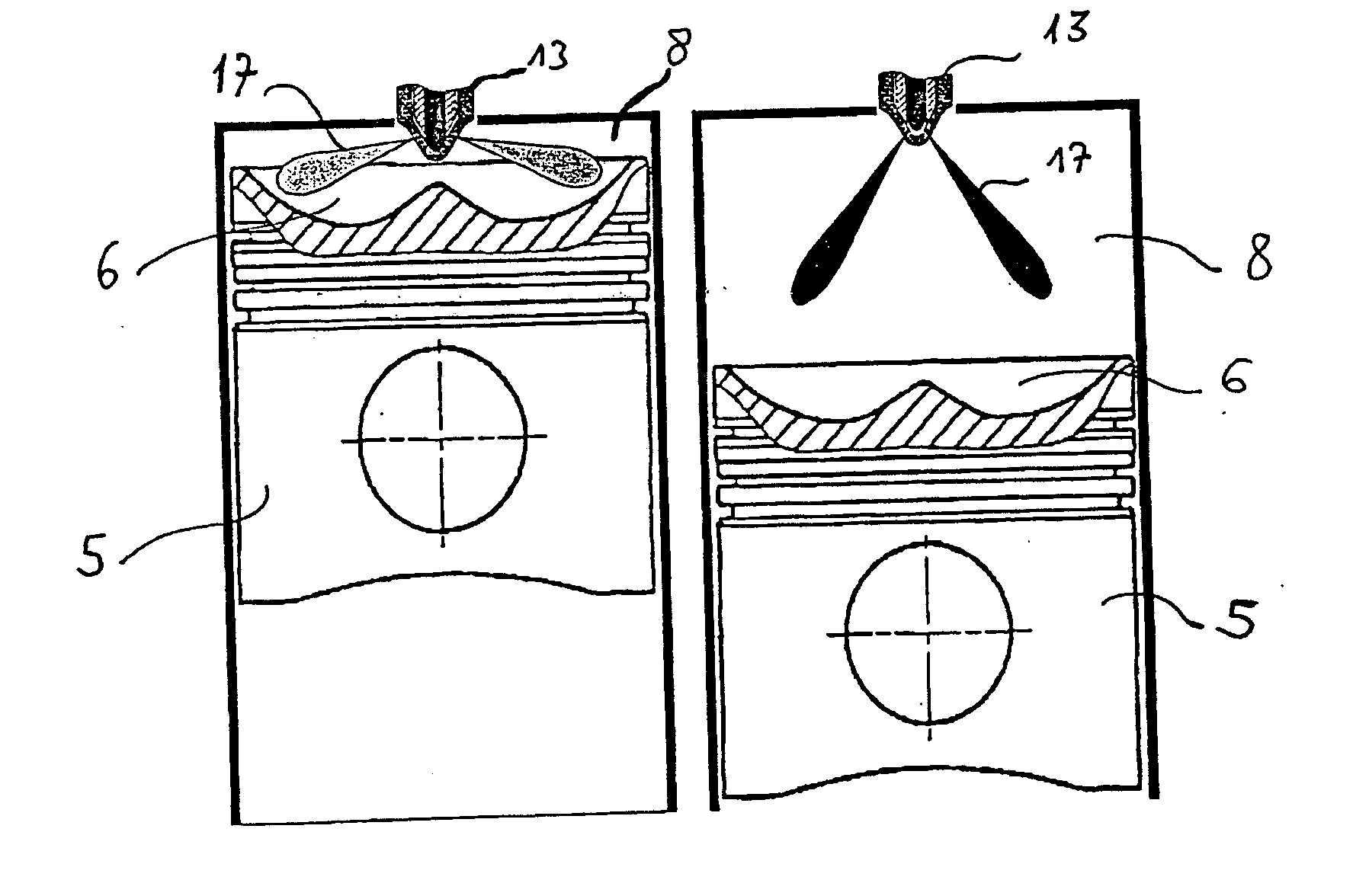
[0012] According to a further refinement of the invention, a swirl movement can be set in the combustion space of the internal combustion engine. Preferably, a generated fuel cloud of a fuel jet (17) is offset or laterally displaced by the swirl movement set in the combustion space, in particular during a fuel injection carried out intermittently. As a result, for example, the formed fuel cloud of a part quantity, when it penetrates through the combustion space, can be laterally displaced, in particular in the direction of a cylinder wall. The fuel jets or the fuel droplets are thus moved away or moved further from the cylinder wall during their propagation, so that they are intermixed with the combustion space air or evaporate, in particular during preinjection and postinjection, before they reach the cylinder wall. A wall accretion of fuel in the cylinder is thus largely prevented. If there is no swirl movement in the combustion space, the fuel jet is propagated along an injection-hole center axis and impinges onto the cylinder wall on account of the short travel up to the cylinder wall. Furthermore, in this case, the preceding jet parcels or the jet parcels emerging first from the injection nozzle form a jet duct which results in an accelerated penetration of the following jet parcels or part quantities due to a lee effect, so that, in the absence of a swirl movement of the combustion space, an impingement of fuel onto the cylinder wall becomes more likely.
[0015] According to a further refinement of the invention, the piston recess has, starting from the piston head, first, a flat entry with a low curvature and, from the region of the maximum recess depth, a greater curvature extending into the piston recess projection. This prevents an accretion of fuel in the region of the piston head and thus achieves a minimization of exhaust gas emissions. Preferably, the piston recess projection has a cone angle in a range of 90° to 160°.

Problems solved by technology

Experience has nevertheless shown that, in spite of the measures proposed above, increased exhaust gas emissions continue to occur.
A desired throttling action can thereby be achieved in a controlled way in the seat of the nozzle needle and gives rise to an unstable cavitating flow in the injection bores of the injection nozzle.

Method used


Image

  • Compression-ignition internal combustion engine
  • Compression-ignition internal combustion engine
  • Compression-ignition internal combustion engine

Examples


Embodiment Construction

[0026]FIG. 1 shows an internal combustion engine 1, in which a crankshaft 2 is driven via a connecting rod 4 by a piston 5 guided in a cylinder 9. Between the piston 5 and a cylinder head 10, a combustion space 8, which comprises a piston recess 6 introduced into the piston head 7, is formed in the cylinder 9.

[0027] During the clockwise rotation of a crank 3 of the crankshaft 2 on a crank circle 11, the combustion space 8 is reduced in size, the air enclosed in it being compressed. The charge exchange in the combustion space 8 takes place via gas exchange valves and gas ducts, not illustrated, in the cylinder head 10.

[0028] When the crank 3 reaches a top dead center 12, designated below by TDC, the end of compression is reached. The current position of the piston 5 in relation to the cylinder head 10 is defined by the crank angle (p with respect to the top dead center 12.

[0029] An injection nozzle 13 having a plurality of injection bores 21 is arranged centrally in the cylinder h...


PUM


Abstract

The invention relates to an internal combustion engine with a fuel injection device with an injection nozzle having a nozzle needle and a plurality of injection bores. The injection nozzle is arranged to inject fuel into the combustion space in the form of a plurality of fuel jets as a main injection, as a post-injection and / or a preinjection. The injection bores of the injection nozzle are arranged in at least two different separately activatable rows of holes, an operating stroke of the nozzle needle being set by control unit as a function of a piston position and / or an operating point of the engine, and the rows of holes of the injection nozzle different injection-hole cone angles.

Description

CROSS-REFERENCE TO RELATED APPLICATIONS [0001] This is a U.S. National Phase of International Application No. PCT / DE02 / 04205, filed Jun. 25, 2004, and claims the benefit of priority under 35 U.S.C. §119 based on DE 10329524.0, filed Jun. 30, 2003, the entire disclosures of which are incorporated herein by reference.BACKGROUND AND SUMMARY OF THE INVENTION [0002] The invention relates to a compression-ignition internal combustion engine, in which fuel is injected into a combustion space by an injection nozzle having a plurality of injection bores. [0003] In direct-injection internal combustion engines with compression ignition, for the configuration of a load-dependent fuel injection, injection nozzles are used in which the configuration of the injection profile is controlled by a corresponding construction of the injection nozzle. This is intended to improve mixture preparation in the combustion space and therefore the formation of emissions in the exhaust gas. Furthermore, the funct...

Claims


Application Information

Patent Timeline
IPC IPC(8): F02B3/10F02B1/12F02B3/06F02B23/06F02F1/40F02M45/08F02M61/16F02M61/18F02M63/00F02M63/02
CPCF02B1/12Y02T10/123F02B23/0624F02B23/0651F02B23/0669F02B23/0696F02B2275/14F02D41/402F02F1/40F02M45/086F02M61/161F02M61/1806F02M63/0225Y02T10/125Y02T10/44F02B3/06Y02T10/12Y02T10/40
Inventor BLESSING, MATTHIASBRAUN, HARALDKOENIG, GERHARDKRUEGER, CHRISTIANRAAB, ALOIS
Owner DAIMLER AG
Why Eureka
Try Eureka