
Brushless direct current (DC) electric generator with decreased electromagnetic drag

a direct current, electric generator technology, applied in the direction of dynamo-electric machines, synchronous machines, electrical apparatus, etc., can solve the problems of not all electrons involved in the structure of materials, the cost of superconducting solutions is well known, and the availability, reliability and expense of renewable energy sources such as solar, wind, hydroelectric and other problems, to achieve the effect of reducing electromagnetic drag and producing electric power at greater efficiency

Inactive Publication Date: 2012-08-16
HOLCOMB ROBERT RAY
View PDF0 Cites 8 Cited by
  • Summary
  • Abstract
  • Description
  • Claims
  • Application Information

AI Technical Summary

Benefits of technology

"This patent describes an electric machine that produces power with high efficiency and low drag. The machine includes a stator with slots and an armature insert with permanent magnet rotors. The armature insert is divided into sections and can be rotated to align with the slots, creating a moving excitation field that induces a current flow. The machine also includes a synchronized rotation of the armature insert members, which reduces drag and improves efficiency. The technical effects of this design include reduced drag, improved efficiency, and reduced noise."

Problems solved by technology

Renewable energy sources such as solar, wind, hydroelectric, electrostatic, temperature differential and geothermal energy have significant problems of availability, reliability and expense.
While such gains are attractive, the expenses and challenges of implementing superconducting solutions are well known.
Further, not all electrons are involved in the structure of material.
If the load current in the generator conductors increases, the drag associated with the reaction force increases.
Increasing drag and increasing load current leads to decreasing conversion efficiency and can eventually lead to destructive consequences for generator equipment.

Method used


Image

  • Brushless direct current (DC) electric generator with decreased electromagnetic drag
  • Brushless direct current (DC) electric generator with decreased electromagnetic drag
  • Brushless direct current (DC) electric generator with decreased electromagnetic drag

Examples


Embodiment Construction

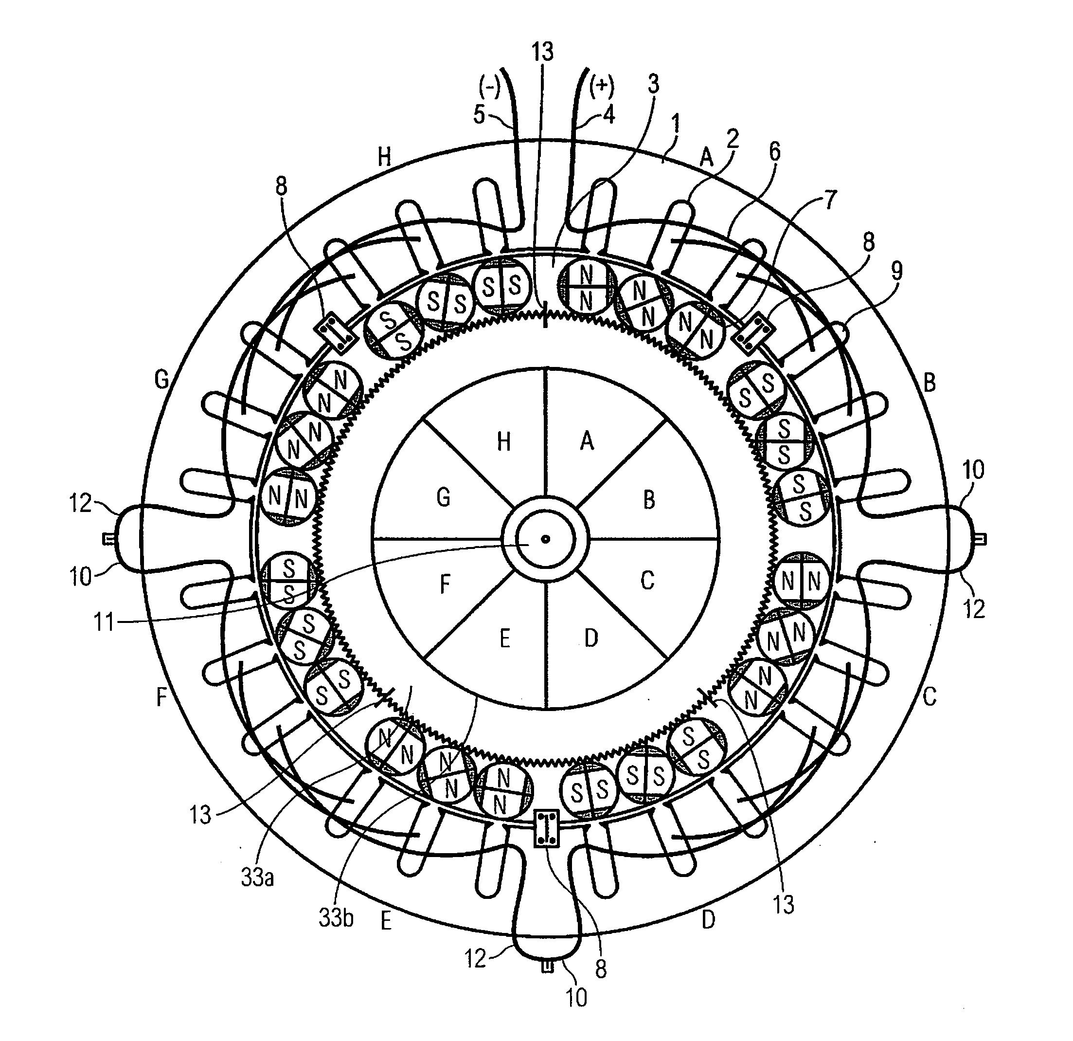
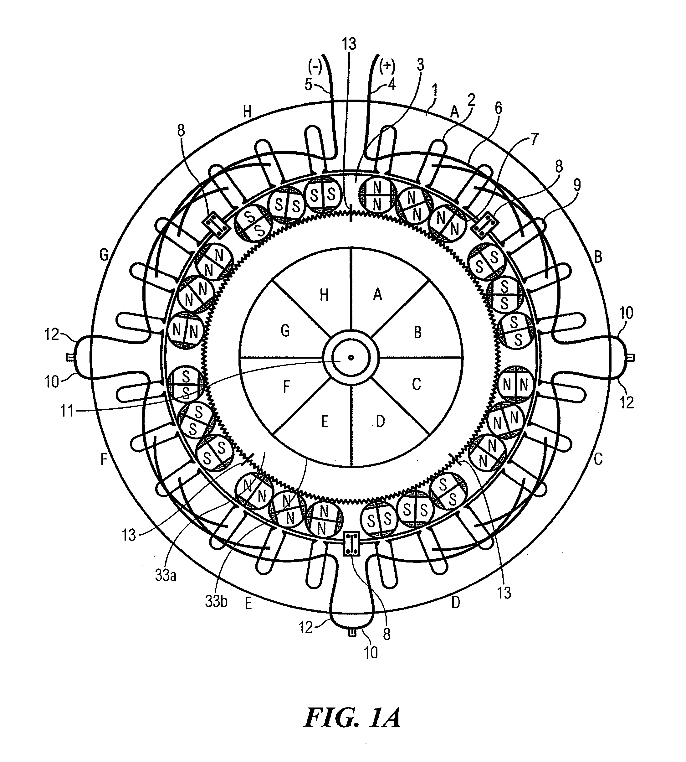
[0036]In accordance with various exemplary embodiments discussed and described herein, and by way of brief summary, motor reaction force may be reduced and other problems can be solved in an embodiment where a stator insert into which is inserted shielded bipolar permanent magnets, also known as slot rotors or the like, but which are referred to herein as armature inserts, that rotate on their axis over each wire slot of the stator can constitute an inventive generator. The permanent magnets of the armature inserts can be contained within a shielded laminated cylinder that can be constituted of mu metal and can be laminated, for example, using steel, such as austenitic stainless steel lamination pieces or the like. The cylinder serves to shield the laminated ferromagnetic pole pieces of the stator from the magnetic fields generated by the permanent magnets of the armature inserts such that only the winding slots are exposed thereto. The cylinder may be constituted at the same length...


PUM


Abstract

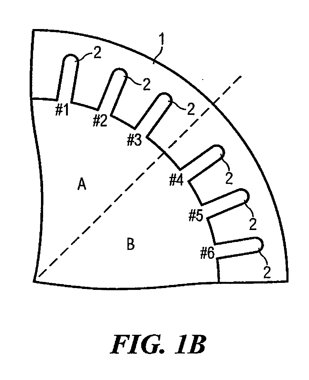
A method and apparatus for reducing drag in an electric generator are disclosed. Armature insert members are distributed along a periphery of a stator insert fit into a stator having induction windings arranged in slots. The armature insert members include permanent magnet rotors having a pair of pole sections with same magnetic polarity. The alignment of the armature insert members is offset in 45 degree increments. The armature insert members are rotated together in a synchronized manner such that the pole sections are sequentially rotated into alignment with the slots providing a moving excitation field. The stator insert and the stator are divided into sectors from a common center point. Armature insert members having a first magnetic polarity are inserted into positions around the outer periphery of the stator insert corresponding to first sectors and armature insert members having a second magnetic polarity are inserted into positions around the outer periphery of the stator insert corresponding to second ones of the N sectors, the first ones and the second ones of the N sectors arranged in alternating relation.

Description

FIELD[0001]The present invention relates generally to a decreased drag electric power generating machine, and more particularly, to an electric machine that generates electric power through a series of rotating magnetic bars.BACKGROUND[0002]Rapid consumption of exhaustible energy from the earth, largely in the form of fossil fuels and rapid depletion of associated energy resources and accompanying environmental pollution and climate change drives the clear need for alternative energy supplies. Existing energy supplies must be used more efficiently.[0003]In view of these and other issues, the need for sustainable power generation units is obvious. Renewable energy sources such as solar, wind, hydroelectric, electrostatic, temperature differential and geothermal energy have significant problems of availability, reliability and expense. Even gravity, if it could be efficiently harnessed, could provide a most attractive alternative.[0004]One contribution to increasing consumption effici...

Claims


Application Information

Patent Timeline
Patent Type & Authority Applications(United States)
IPC IPC(8): H02K16/02H02K53/00
CPCH02K53/00H02K21/029
Inventor HOLCOMB, ROBERT RAY
Owner HOLCOMB ROBERT RAY
Learn More