Vehicle lighting device

a technology for vehicle lighting and headlamps, which is applied in vehicle headlamps, transportation and packaging, lighting and heating apparatus, etc., can solve the problems of insufficient illumination, yellowish light that may not be sufficiently combined with blue laser light, and irradiated parts that emit yellowish light, etc., to achieve high illumination, high illuminance area, and high illuminance area

Inactive Publication Date: 2012-08-16
STANLEY ELECTRIC CO LTD
View PDF7 Cites 28 Cited by
  • Summary
  • Abstract
  • Description
  • Claims
  • Application Information

AI Technical Summary

Benefits of technology

[0013]A vehicle lighting device according to one embodiment of the presently disclosed subject matter can include an LED light source, a laser light source, and a fluorescent body that emits visible light in response to excitation light from the LED light source and the laser light source. In addition, while the fluorescent body is emitting the visible light from a front surface thereof, the LED light source is irradiating a rear surface of the fluorescent body with the excitation light, and the laser light source is irradiating, with the excitation light (or laser light), a portion of the front surface of the fluorescent body which is to emit the visible light to a high illuminance area within a light distribution pattern. Consequently, the fluorescent body generates main visible light for creating the light distribution pattern, on the basis of the excitation light from the LED light source, as well as highly bright visible light for creating the high illuminance area within the light distribution pattern, on the basis of the excitation light from the laser light source. This makes it possible to create the high illuminance area, which illuminates a distant area, thus providing the sufficient visibility.
[0014]Furthermore, the rear surface of the fluorescent body is formed to have substantially the same size as a light emitting surface of the LED light source, and is disposed above the light emitting surface so as to cover this whole light emitting surface. In addition, the fluorescent body emits the visible light from the whole front surface located opposite the rear surface, in response to the excitation light from the LED light source. Therefore, the excitation light from the LED light source is irradiated throughout the fluorescent body through the rear surface. Consequently, the appropriately combined visible light is emitted from the whole front surface of the fluorescent body. This prevents color shading from appearing within the light distribution pattern.
[0015]Moreover, the fluorescent body is emitting the visible light from the whole front surface, while the laser light source is partially irradiating the front surface of the fluorescent body with the excitation light (or laser light). Therefore, the front surface of the fluorescent body, which creates a main light source image for the light distribution pattern, emits the especially bright light from the portion thereof on which the excitation light from the laser light source is irradiated, but the whole front surface of the fluorescent body emits the light without creating an unnaturally dark light region. Consequently, as opposed to related vehicle lighting devices in which an LED light source and a fluorescent body create individual regions within a light distribution pattern, the vehicle lighting device according to one embodiment of the presently disclosed subject matter is capable of preventing the gap between the LED light source and the fluorescent body from creating any dark light region within the light distribution pattern, thus restricting the occurrence of illumination nonuniformity within the light distribution pattern.

Problems solved by technology

Accordingly, the light distribution pattern (for example, the pattern of the low beam) which a vehicle lighting device of this type creates may exhibit insufficient illuminance at an area near the cut-off line, which is used to illuminate a distant area.
In this case, it is difficult to provide sufficient visibility.
Consequently, while the part of the fluorescent body which is irradiated with the laser light emits white light as appropriate, the other non-irradiated part emits yellowish light that may not be sufficiently combined with the blue laser light.

Method used


Image

  • Vehicle lighting device
  • Vehicle lighting device
  • Vehicle lighting device

Examples


first embodiment

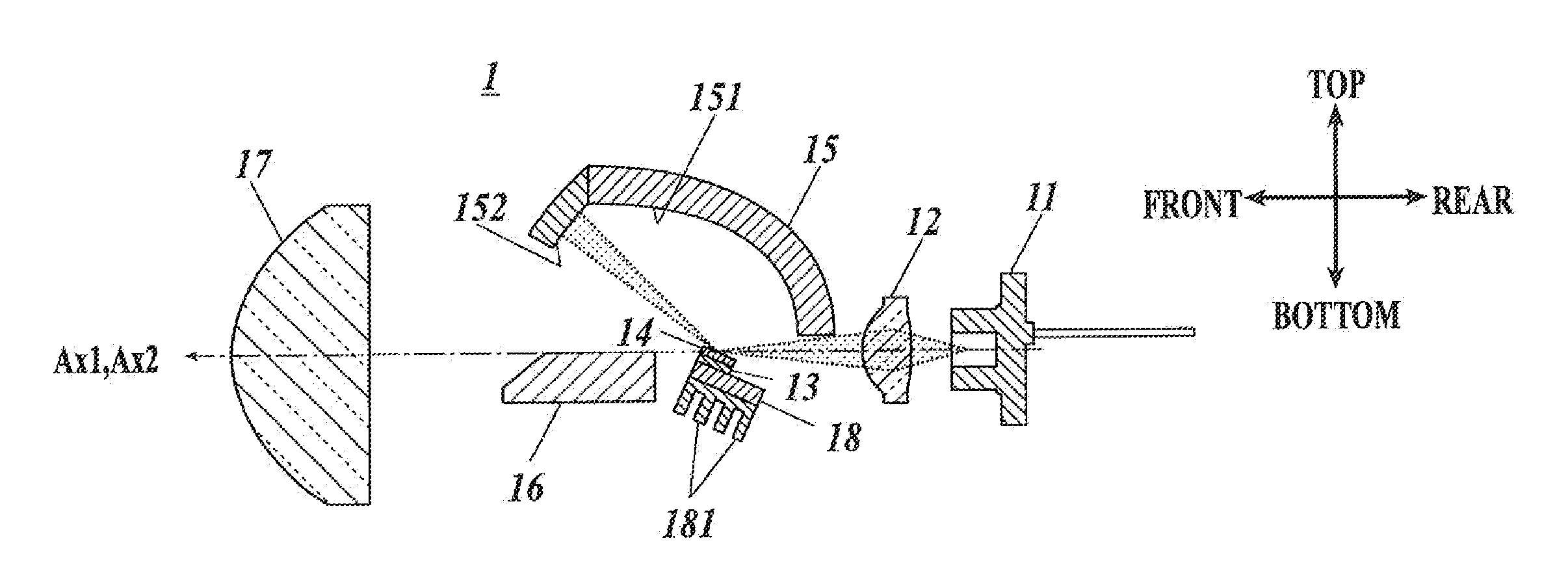
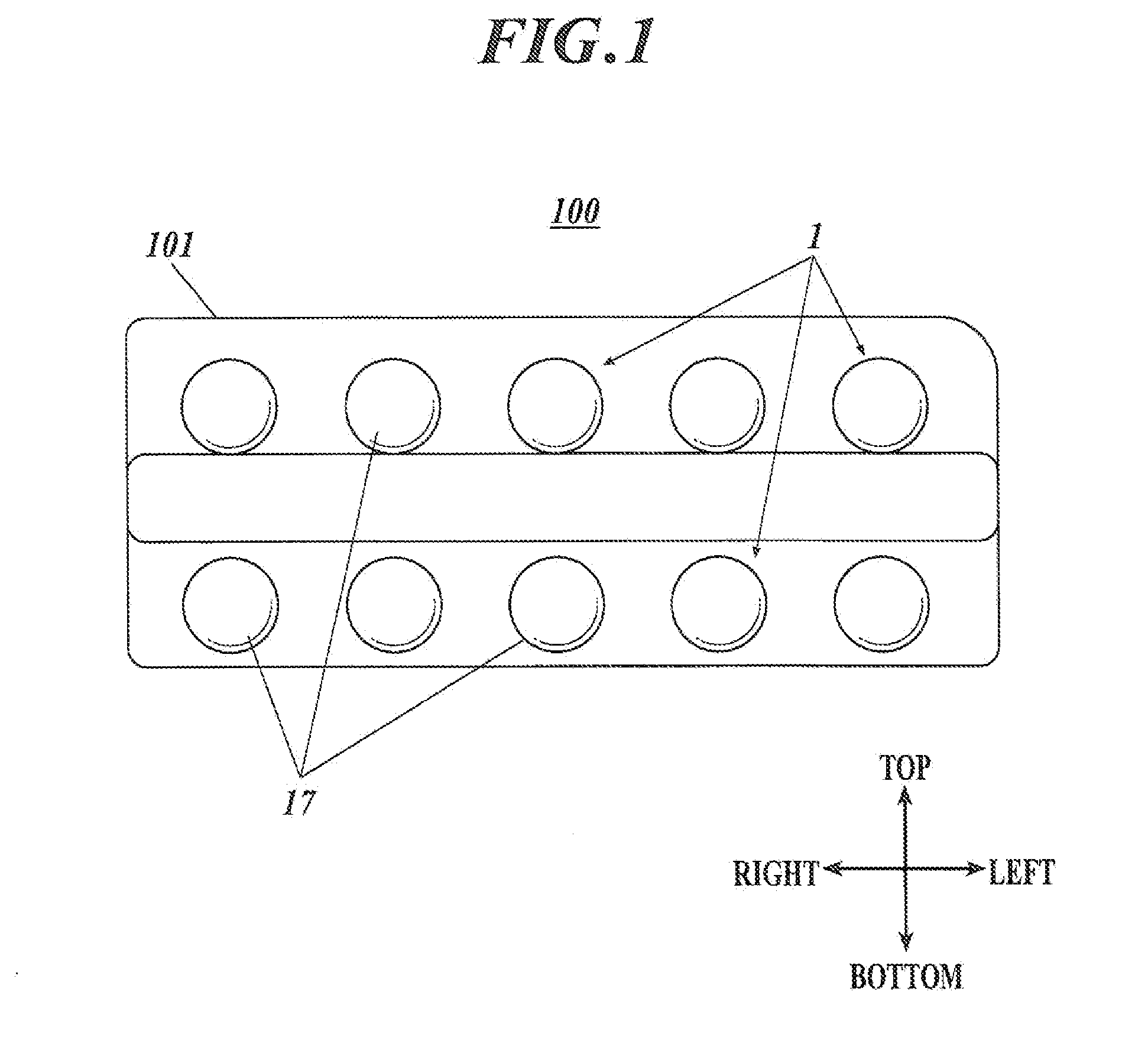
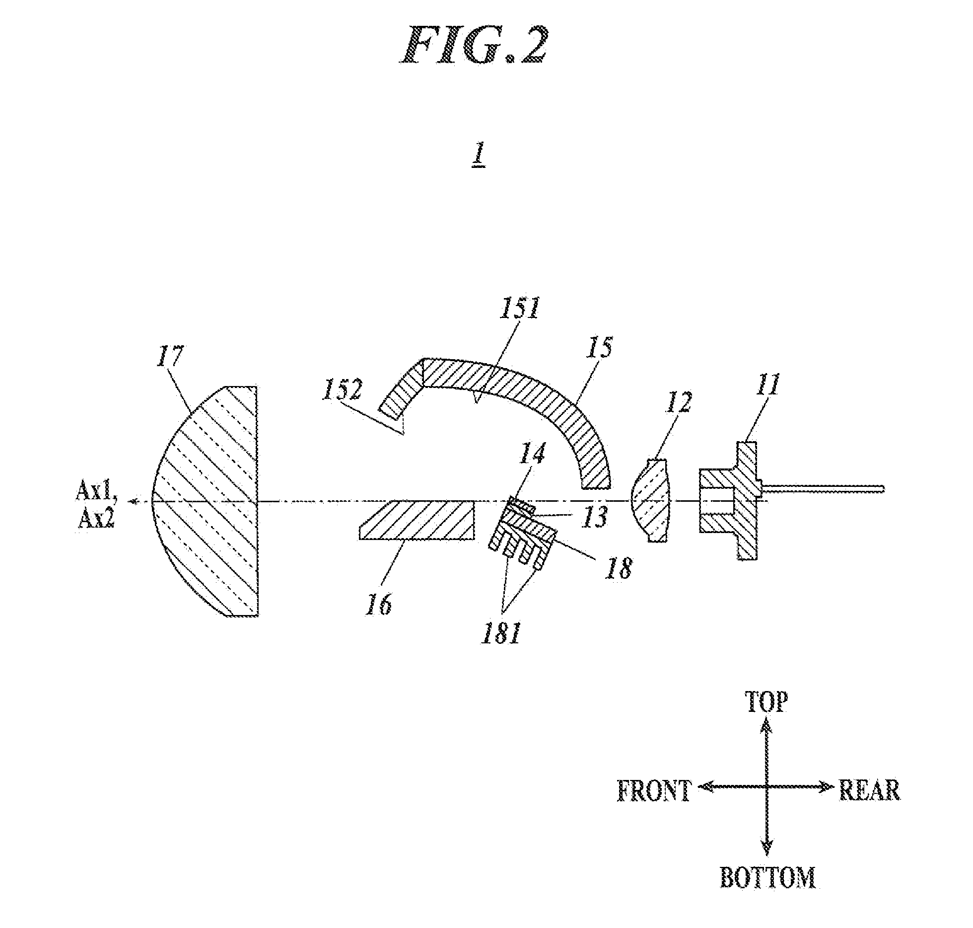
[0032]FIG. 1 is a front view illustrating a headlamp 100 equipped with a vehicle lighting device 1 according to the presently disclosed subject matter, and FIG. 2 is a side cross section view illustrating the vehicle lighting device 1.

[0033]Referring to FIG. 1, the headlamp 100 is equipped with multiple vehicle lighting devices 1 in a lamp room having a front side covered with a transparent cover 101, and the light from each vehicle lighting device 1 creates a predetermined light distribution pattern (the pattern of a low-beam; thereinafter, called a “low-beam pattern”) on the front area of the vehicle.

[0034]Referring to FIG. 2, the vehicle lighting device 1 is a so-called projection type lighting device, and includes a laser diode (hereinafter, called an “LD”) 11, a condenser lens 12, two light emitting diodes (hereinafter, called “LEDs”) 13 and 13, a fluorescent body 14, a reflector 15, a shade 16, and a projection lens 17.

[0035]Specifically, the LD 11 has an optical axis Ax1 exte...

second embodiment

[0055]FIG. 7 is a side cross section view illustrating a vehicle lighting device 2 according to the presently disclosed subject matter.

[0056]Referring to this figure, the vehicle lighting device 2 is a so-called parabolic lighting device, including an LD 11 and a condenser lens 12 that have the same structures as those in the first embodiment, together with two LEDs 23 and 23, a fluorescent body 24, and a reflector 25.

[0057]The LEDs 23 and 23 are arranged in the right-left direction or in the vertical direction with respect to the sheet of FIG. 7, and are inclined toward the rear at an angle of 27.5 degrees with respect to the optical axis Ax1. The other arrangements of the LEDs 23 and 23 are the same as those of the LEDs 13 and 13 of the first embodiment.

[0058]FIG. 8 is a plane view illustrating the fluorescent body 24.

[0059]Referring to this figure, the fluorescent body 24 has a similar structure to the fluorescent body 14 of the first embodiment. However, the fluorescent body 24 ...

third embodiment

[0070]Next, the presently disclosed subject matter will be described.

[0071]FIG. 10 is a view illustrating a side cross section view illustrating a vehicle lighting device 3 according to the third embodiment of the presently disclosed subject matter.

[0072]Referring to this figure, the vehicle lighting device 3 is a so-called direct-projection type lighting device, including an LD 31 and a condenser lens 32, two LEDs 33 and 33, a fluorescent body 34, and a projection lens 37.

[0073]Specifically, the LD 31 has an optical axis Ax1 extending in the rear and obliquely upward direction, and emits blue laser light on the optical axis Ax1 in the rear and obliquely upward direction, for exciting the fluorescent body 34. This LD 31 exhibits the brightness property of the gaussian distribution, which has the highest brightness at the center of the light-emitting portion.

[0074]The condenser lens 32 is located on the optical axis Ax1 in the rear and obliquely upward direction with respect to the L...


PUM


Abstract

A vehicle lighting device can include an LED light source having a light emitting surface, a laser light source, and a fluorescent body for emitting visible light in response to excitation light from the LED light source and the laser light source. The fluorescent body can have a rear surface formed to have substantially the same size as the light emitting surface, and a front surface located opposite the rear surface. The fluorescent body can be disposed on the light emitting surface such that the rear surface covers the whole light emitting surface. The fluorescent body can emit the visible light from the whole of the front surface, in response to the excitation light from the LED light source. The laser light source irradiates the excitation light to a portion on the front surface. The portion is to emit the visible light to a high illuminance area within a light distribution pattern.

Description

[0001]This application claims the priority benefit under 35 U.S.C. §119 of Japanese Patent Application No. 2011-026682 filed on Feb. 10, 2011, which is hereby incorporated in its entirety by reference.FIELD[0002]The presently disclosed subject matter presently disclosed subject matter relates to a vehicle lighting device.DESCRIPTION OF RELATED ART[0003]In recent years, light sources with a light emitting diode (LED) are being increasingly applied to vehicle lighting devices such as headlamps for vehicles. Such vehicle lighting devices are superior in terms of power consumption, etc., but the brightness of an LED is lower than that of other light sources such as high intensity discharge (HID) lamps. Accordingly, the light distribution pattern (for example, the pattern of the low beam) which a vehicle lighting device of this type creates may exhibit insufficient illuminance at an area near the cut-off line, which is used to illuminate a distant area. In this case, it is difficult to p...

Claims


Application Information

Patent Timeline
Patent Type & Authority Applications(United States)
IPC IPC(8): F21V9/16B60Q1/00F21V13/00
CPCF21S48/1131F21S48/1159F21S48/1163F21S48/1388F21S48/1225F21S48/1323F21S48/1382F21S48/1195F21S41/125F21S41/147F21S41/155F21S41/18F21S41/285F21S41/255F21S41/321F21S41/322F21S41/338F21S41/43F21S45/47F21S41/16F21S41/365F21S41/176
Inventor NAKAZATO, YOSHIAKINAKAYA, YOSHIAKI
Owner STANLEY ELECTRIC CO LTD
Why Eureka
Try Eureka