Method And Apparatus For Signal Compression And Decompression

a signal compression and decompression technology, applied in electrical equipment, code conversion, multi-carrier systems, etc., can solve problems such as limited processing delays, and achieve the effect of lowering the required transport data rate and lowering the data ra

Active Publication Date: 2012-08-16
ALCATEL LUCENT SAS
View PDF8 Cites 48 Cited by
  • Summary
  • Abstract
  • Description
  • Claims
  • Application Information

AI Technical Summary

Benefits of technology

[0002]Example embodiments provide a compression scheme that lowers the required transport data rates. For example, in Long Term Evolution (LTE), an embodiment results in approximately 3.5 times lower data rates than in the case of uncompressed I / Q transmission.
[0005]In addition, the example embodiment introduce limited processing delay (i.e., compression and decompression latency), compared to the uncompressed version.
[0009]In one embodiment, the method of compressing a digital signal includes reducing redundancies in the digital signal, scaling a block of samples output from the reducing step by a scaling factor, and quantizing the scaled samples to produce compressed samples. The digital signal being compressed may be a digital radio frequency signal.

Problems solved by technology

In addition, the example embodiment introduce limited processing delay (i.e., compression and decompression latency), compared to the uncompressed version.

Method used


Image

  • Method And Apparatus For Signal Compression And Decompression
  • Method And Apparatus For Signal Compression And Decompression
  • Method And Apparatus For Signal Compression And Decompression

Examples


example implementation

[0067]As one embodiment we present implementation of the above solution to compress and transport a 10 MHz LTE signal.

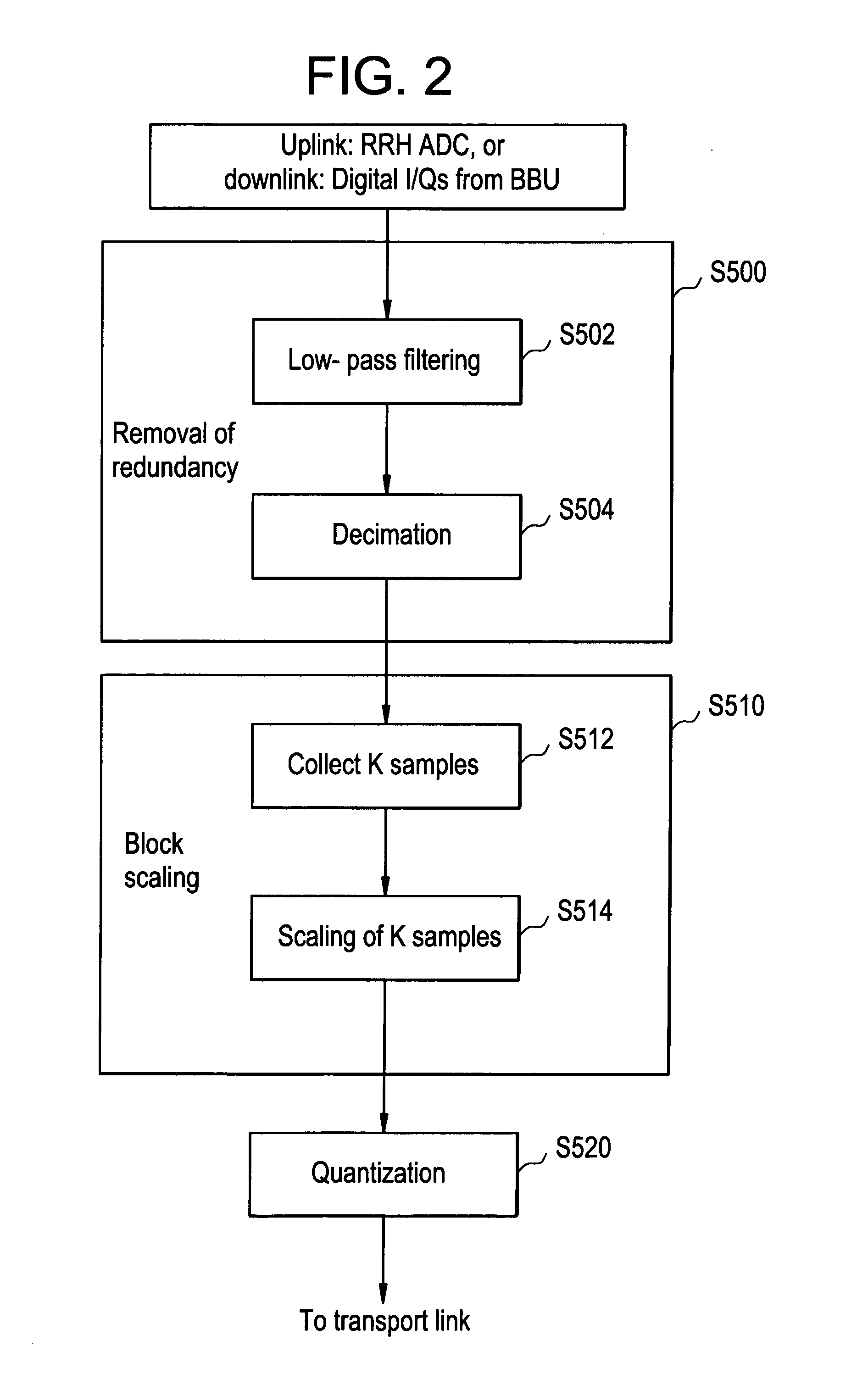
[0068]In FIG. 6, an example of the 10 MHz LTE spectrum is presented using a sample rate of 15.36 MHz. Approximately one-third of the spectrum carries no information relevant to the LTE transmission. Therefore we have applied multi-rate filtering to lower the sample rate from 15.36 MHz down to 10.32 MHz. The filtering is implemented as a low-pass FIR filter, with the sinc(t) impulse response which is shaped using the Hamming window. In this example, the latency incurred by the filtering is 2.08 usec.

[0069]Note that there is nothing particular to the output sample rate which is in this example set to 10.32 MHz. Other sampling frequencies may be also considered to make the implementation easier. For example, 10.24 MHz is a ⅔ of the initial 15.36 MHz sampling rate, which may be more suitable for a possible ASIC / FPGA implementation.

[0070]Block scaling (step S510) is perfo...


PUM


Abstract

In one embodiment, the method of compressing a digital signal includes reducing redundancies in the digital signal, scaling a block of samples output from the reducing step by a scaling factor, and quantizing the scaled samples to produce compressed samples. The digital signal being compressed may be a digital radio frequency signal.

Description

BACKGROUND OF THE INVENTION[0001]In a number of wireless base-station solutions baseband units (BBUs) and radio subsystems are separate and physically remote. In those solutions the antennas, radio-frequency front-end and analog-to-digital interface are a part of remote-radio heads (RRHs). The RRHs are connected to the BBUs via a digital transport network. Digitized baseband complex inphase (I) and quadrature (Q) samples are transported over the transport links between the RRHs and BBUs. In many wireless technologies (3G and 4G), transmission of I / Q samples requires high data rates and allocation of significant transport network resources in terms of communication bandwidth as well as good performance such as low latency and jitter. Thus, a reduction in the resources required to transport I / Q samples will result in a commensurate reduction in the cost of the transport.SUMMARY OF THE INVENTION[0002]Example embodiments provide a compression scheme that lowers the required transport da...

Claims


Application Information

Patent Timeline
Patent Type & Authority Applications(United States)
IPC IPC(8): H04B1/66
CPCH03M7/30H04L27/32
Inventor SAMARDZIJA, DRAGAN M.PASTALAN, JOHNMACDONALD, WILLIAM M.VALENZUELA, REINALDO A.
Owner ALCATEL LUCENT SAS
Why Eureka
Try Eureka