Method for Controlling Delivery Quantity, and Reciprocating Compressor Having Delivery Quantity Control

a reciprocating compressor and quantity control technology, applied in the direction of pump components, positive displacement liquid engine, pump control, etc., can solve the problems of high stress-requiring, high maintenance effort, and relatively high wear of the closing body of the intake valve and the pressure valve, so as to achieve the effect of reducing the risk of damage, and improving the service li

Inactive Publication Date: 2012-08-16
BURCKHARDT COMPRESSION AG
View PDF4 Cites 10 Cited by
  • Summary
  • Abstract
  • Description
  • Claims
  • Application Information

AI Technical Summary

Benefits of technology

[0006]In particular, the problem is solved by a method for delivery quantity control of a reciprocating compressor, in which the movement of a closing body of a self-acting intake valve is influenced during at least part of a cycle of crank rotation by an unloader driven by a control device, wherein the method comprises a continuously variable backflow regulation, in which the unloader lies against the closing body during a first section of the cycle of crank rotation and prevents its closure, and in which the unloader is driven back during a second section of the cycle of crank rotation and the closing body is closed, wherein the unloader is driven back in such a way that the speed of the moving closing body is reduced prior to its seating on the intake valve.
[0008]In the method according to the invention, the delivery quantity is regulated by the forced holding open of the intake valve. In the course of doing this, preferably two different regulation methods are used, namely a skip regulation and the continuously variable backflow regulation. Both methods employ a so-called unloader, which presses the closing body of the valve, for example a plate valve, ring valve or poppet valve, into an open position and preferably, onto the valve seat.
[0009]The reciprocating compressor has a compression space, to which gas is introduced via an intake valve and from which compressed gas is led away via an outlet valve, also called pressure valve. In the skip regulation method, the closing body of the intake valve is held open during a whole working stroke or a complete work cycle. This causes the pressure in the compression space to not rise above the pressure required to open the pressure valve during the compression phase, such that the aspirated gas is pressed back into the intake conduit during the compression phase and thus compression and further transport into the pressure conduit are not available. The pressure valve thus remains shut and thus this compression space does not convey any gas via the pressure valve into the pressure conduit. If skip regulation is deactivated, i.e. normal operation executed, then the compression space again conveys the whole gas stream via the pressure valve into the pressure conduit. If the reciprocating compressor has, for example, only one compression space, then skip regulation may be run such that certain working cycles are executed normally and skip regulation is activated during certain working cycles. In this way, a disadvantage of skip regulation is that the amount of gas conveyed from the reciprocating compressor can only be regulated in a stepwise manner. A further disadvantage of skip regulation is that there is no flow through the unloaded compression space, i.e. with non-opening pressure valve, and thus dirt can collect in the compression space, which raises valve wear or respectively wear of the packing rings and piston rings.
[0010]In the backflow regulation method, the intake valve is held open with the help of the unloader during a partial angular range of a complete compression stroke or respectively of a complete crank rotation and thereafter is shut, in order to thereby influence the delivery quantity. In doing this, the intake valve is only pressed open by the unloader at the beginning of the compression phase. In this way, a part of the gas in the compression space is pressed back into the intake conduit. As soon as the closing body of the intake valve completely closes, the gas remaining in the compression space is compressed and pressed into the pressure conduit via the pressure valve. In this way, during backflow regulation, only a part of the maximum-possible gas stream is conveyed from the compression space into the pressure conduit via the pressure valve.
[0011]With the backflow regulation method, the fact that the opening time of the self-acting pressure valve is reduced proportionately for smaller delivery quantities is disadvantageous, as is the fact that for delivery quantities of less than 40% of the rated delivery quantity the opening time of the pressure valve is reduced to such an extent that the opening and shutting speeds of the pressure valve can increase by multiples. On the one hand, this leads to increased wear of the self-acting pressure valve and, on the other hand, this reduces the range within which partial delivery quantities may be reliably conveyed. A further disadvantage of backflow regulation is that the gas is more strongly heated prior to compression due to the longer dwell time in the compression space and due to heat transfer via the cylinder wall and due to a leak stream via the piston. This results in the gas on the pressure side having a raised temperature.
[0012]In an advantageous embodiment, the method according to the invention has the advantage that, through combined use of back flow regulation and skip regulation, the quantity delivered by the reciprocating compressor can be varied across a wide range, in particular with no additional wear of the closing body of the intake valve and / or pressure valve. For regulation of the delivery quantity, there are essentially preferably three different methods available which may be used. Alongside a method with maximal delivery quantity, in which the intake valve shuts automatically, also the backflow regulation method as already described and the skip regulation method as already described. For example, regulation dependent on the quantity of fluid to be delivered at any particular time may be brought about as follows:
[0014]For large delivery streams, i.e. delivery quantities in the range of between about 100% and 80% of the maximal delivery quantity, continuously variable backflow regulation is deployed. Although it is also possible that not every cycle of crank rotation is regulated with backflow regulation, but rather that the intake valve is operated automatically (i.e. without exerting influence), for example , for one or two cycles. This method has the advantage that the unloader is called for less such that longer service life results and that quantity regulation itself uses up less energy.
[0015]For medium-sized delivery streams, i.e. with delivery quantities in the range of between about 80% and 50% of the maximal delivery quantity, continuously variable backflow regulation is used for each cycle.

Problems solved by technology

This method has the disadvantage that the compressor valves, as used on the intake side and, in particular, those used on the pressure side, still have a high stress-requirement, particularly when the compressor system is run using continuously variable backflow regulation methods.
A disadvantage of this known method is the fact that the closing body of the intake valve and of the pressure valve is subject to relatively high wear, which requires a correspondingly high maintenance effort.

Method used


Image

  • Method for Controlling Delivery Quantity, and Reciprocating Compressor Having Delivery Quantity Control
  • Method for Controlling Delivery Quantity, and Reciprocating Compressor Having Delivery Quantity Control
  • Method for Controlling Delivery Quantity, and Reciprocating Compressor Having Delivery Quantity Control

Examples


Embodiment Construction

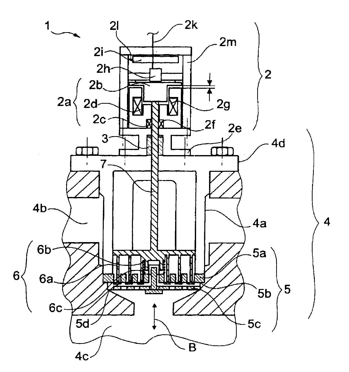
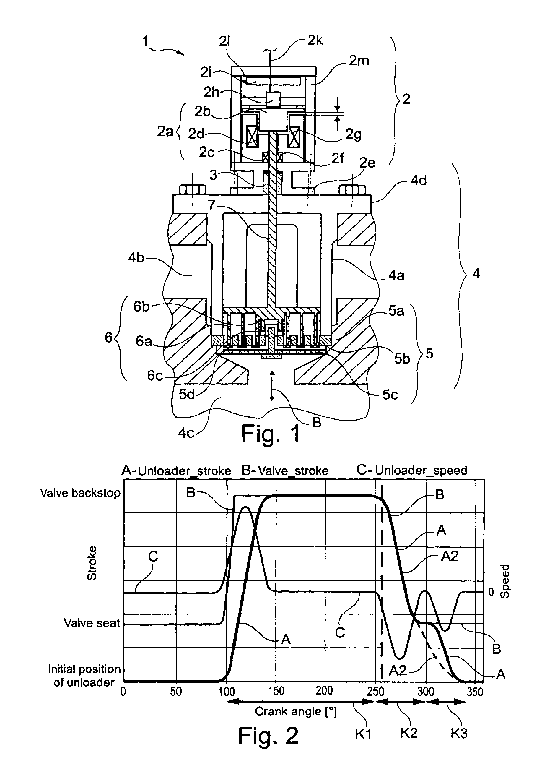
[0032]FIG. 1 shows a longitudinal cross-section through a controllable valve 1 comprising a compressor housing 4 with an intake valve 5 arranged therein, whose position is influenced by an unloader 6, wherein the unloader 6 is actuated by a control device 2, arranged outside of the compressor housing 4, via a connection means 7, in the form of a connection rod.

[0033]The compressor housing 4 comprises a lamp 4a, a gas space 4b, a compression space 4c and a cover 4d, wherein the compressor housing 4 also comprises a non-depicted or, as the case may be, an unseen pressure valve 8, via which the compressed fluid may escape from the compression space 4c. The self-acting intake valve 5 comprises a valve seat 5a, a closing body 5b, which is mounted so as to be movable in a stroke direction B and is referred to in the following as valve plate 5b, a valve backstop 5c, as well as a return spring 5d. The unloader 6 comprises a plurality of gripper extensions 6a or fingers 6a, a guide 6b as wel...


PUM


Abstract

The invention relates to a method for delivery quantity control of a reciprocating compressor, wherein the motion of a closing organ (5b) of an automatic suction valve (5) is influenced during at least one part of a cycle of the crankshaft by means of a refraction gripper (6), wherein the method comprises a continuously variable return flow control, wherein the retraction gripper (6) contacts the closing organ (5b) and prevents the same from closing during a first partial segment (K1) of the cycle of the crankshaft, and wherein the retraction gripper (6) is retracted during a second partial segment (K2) of the cycle of the crankshaft and the closing organ (5b) is closed, wherein the retraction gripper (6) is retracted such that the speed of the moving closing organ (5b) is reduced prior to contacting the suction valve (5).

Description

[0001]The invention concerns a method for controlling delivery quantity of a reciprocating compressor according to the preamble of claim 1. The invention further concerns a reciprocating compressor with delivery quantity control according to the preamble of claim 12.BACKGROUND ART[0002]Documents EP 0 801 227 A2 and EP 1 400 692 disclose a method for influencing the pressure-dependent, self-acting, periodic opening movement of a closing body of an intake valve of a reciprocating compressor by means of a control device which influences the closing body, as necessary, over at least a part of the crank rotation. Since the service life of self-acting compressor valves, as mostly used on the intake and the pressure side, is primarily influenced by the impact-stress-requirement of the alternating impingement of the actual closing body on, respectively, the seat or backstop, the above-mentioned documents disclose a method in which the intake valve is forcefully opened before reaching pressu...

Claims


Application Information

Patent Timeline
Patent Type & Authority Applications(United States)
IPC IPC(8): F04B49/22
CPCF04B39/08F04B2205/05F04B49/246F04B49/243
Inventor ALLENSPACH, ANDREASAIGNER, ROLAND
Owner BURCKHARDT COMPRESSION AG
Why Eureka
Try Eureka