Hydropneumatic riveter

a riveter and hydropneumatic technology, applied in forging presses, manufacturing tools, forging/pressing/hammering apparatus, etc., can solve the problems of inability to access tightly confined areas, inability to access internal wing structures, and relatively heavy units for operators to hold, so as to reduce the size and weight of the forming portion, the effect of high compactness and light weigh

Active Publication Date: 2012-08-23
HY TECH MACHINE
View PDF11 Cites 12 Cited by
  • Summary
  • Abstract
  • Description
  • Claims
  • Application Information

AI Technical Summary

Benefits of technology

[0010]A primary object of the present invention is to create a highly compact and lightweight riveter. The present invention accomplishes this by separating the force generation portion (pressure intensifier) of the riveter from the rivet forming portion (forming head) of the riveter. Control of the riveter is packaged at the force generation portion to further reduce the size and weight of the forming portion. The pressure intensifier of the riveter comprises a low pressure air actuated piston, which is attached to a high pressure hydraulic piston. The forming head of the present invention comprises a piston housing and a moving piston, which interfaces with the rivet to be compressed or pulled. The two portions are connected via a flexible metal-braided conduit and a quick disconnect fitting may also be employed. By separating these two portions, the forming head of the present invention can fit into more tightly confined areas, and the riveter is lighter for the operator to hold. The weight reduction for the rivet squeezer forming head of the present invention is approximately 3 lb, or 60% of the weight of a pneumatic squeezer with similar force capability. Those skilled in the art can readily appreciate the advantages of such a compact and lightweight riveter.
[0011]Another object of the present invention is to produce a riveter with a constant actuation force. The rivet squeezer of the present invention utilizes a compression pin driven by hydraulic pressure only, and as such the force does not vary with varying rivet lengths. This is in contrast to rivet squeezers of the known art, whereby the compression force varies as the rivet is squeezed. The variability is due to the fact that the rivet is compressed by a pin or jaw which is further driven by an air piston driven profiled wedge. As the interfacing tip of the pin or jaw moves in relation to the profiled wedge, the mechanical advantage changes. For a ⅛ inch rivet being squeezed, it is necessary to upset the shank of the rivet by approximately 0.110 inch. However the inventor has found that a typical pneumatic squeezer force may drop from 3,800 lbf to only 2,000 lbf in 0.030 inch of travel of the profiled wedge. Those skilled in the art will recognize that this variability may require the operator to make additional adjustments to the squeezer, or require the operator to squeeze the rivet twice to set the final rivet head size.
[0012]A further object of the present invention is to produce a riveter which is more cost effective, by offering greater flexibility to the operator. The present invention allows the operator to purchase one force generation portion to power a variety of rivet forming portions, thereby saving the expense of multiple force generation portions. A disadvantage of existing riveters is related to their intrinsic inseparable assembly. Since the force generation portion and forming head portion of these riveters are inseparable, the end user is essentially buying additional force generation portions each time a different forming head is needed, which results in a higher cost burden to the operator.

Problems solved by technology

A first disadvantage of existing riveters is the inability to access some tightly confined areas, such as internal wing structures.
Although recent inventions have attempted to minimize the size of the unit, such as that for an alligator type squeezer detailed in U.S. Pat. No. 7,290,431 by Boris Spivak, the size of these units still prohibit access to some confined structural areas.
However, despite an attempt to allow for greater flexibility of the unit referenced by employing a rotational head, the unit is still prohibited from very confined areas, and it makes for a relatively heavy unit for the operator to hold.

Method used


Image

  • Hydropneumatic riveter
  • Hydropneumatic riveter
  • Hydropneumatic riveter

Examples


Embodiment Construction

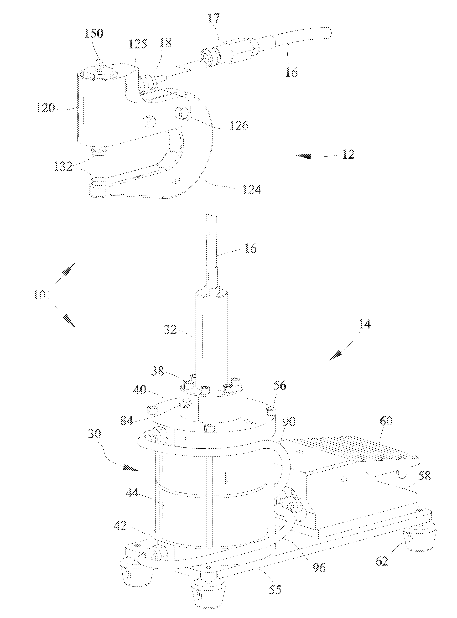
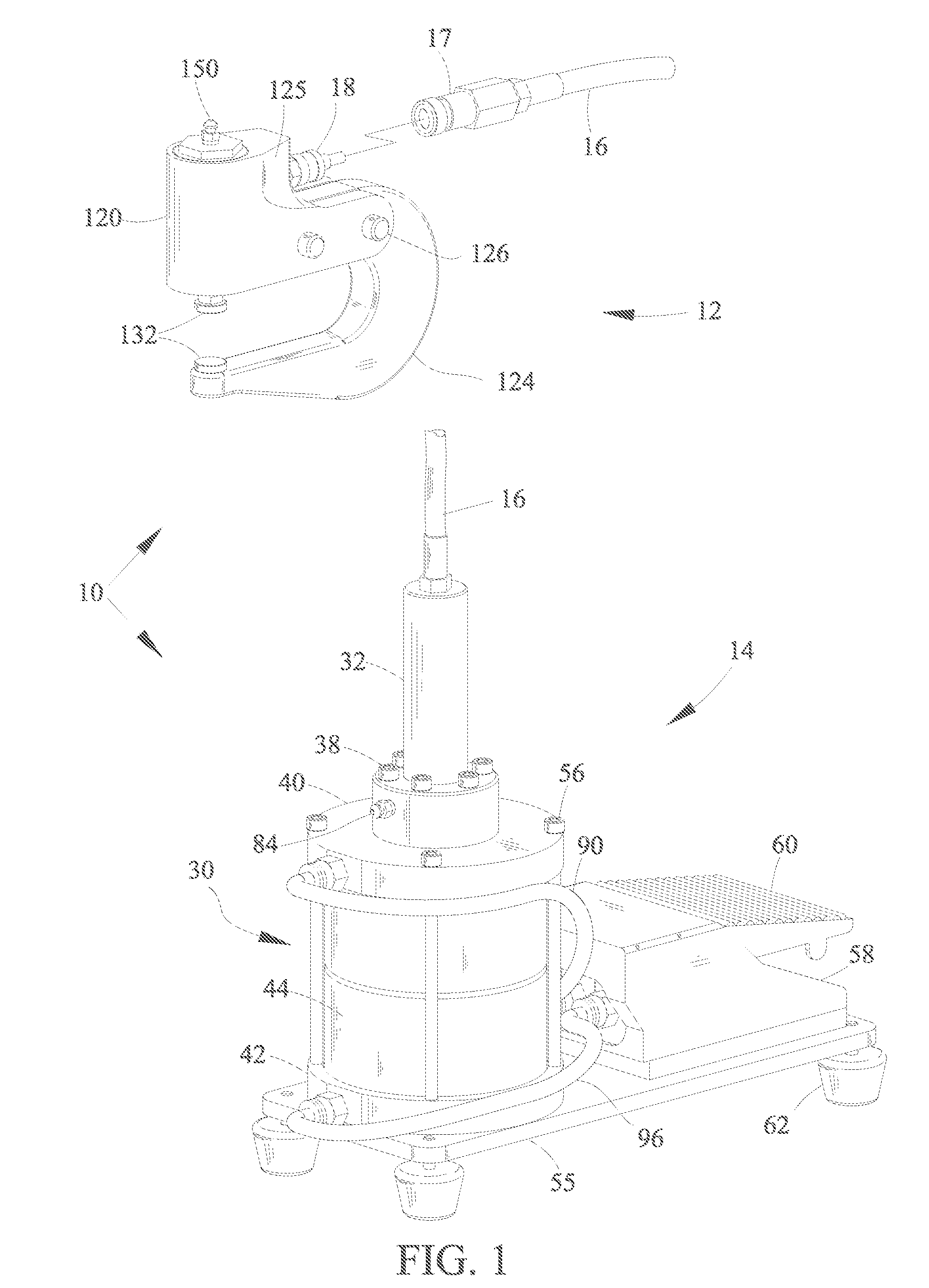
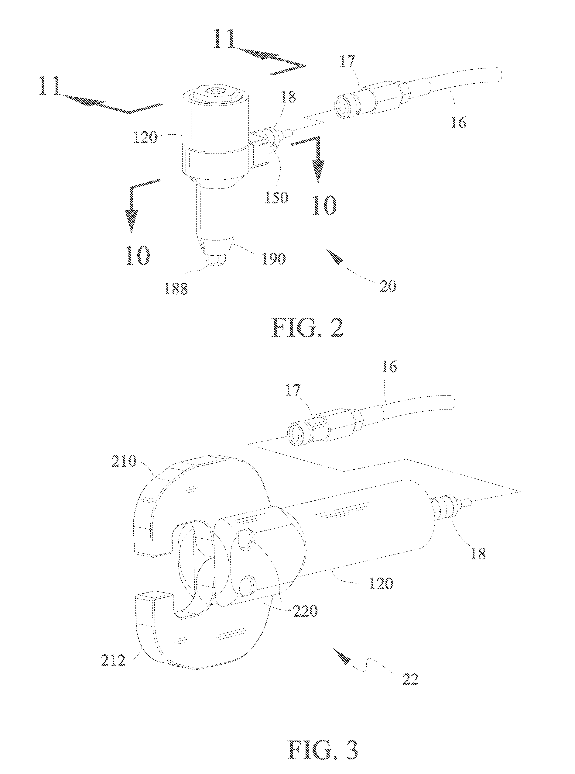
[0027]According to a preferred embodiment of the invention, there is described a hydropneumatic riveter having features that allow for a more compact size, lower weight, consistent force and greater versatility. Referring to FIG. 1, a hydropneumatic riveter 10 can be generally divided into two main sub-assemblies; a forming head 12 and a pressure intensifier 14. The forming head 12 shown in FIG. 1 is a C-yoke type, so named due to the shape of the anvil which forms the rivet. The two sub-assemblies are interconnected via a flexible wire-braided reinforced conduit 16, which may comprise a fluid-tight female quick disconnect 17. The conduit 16 is generally permanently attached to the pressure intensifier 14, but could alternately be permanently attached to the forming head 12. The forming head 12 may likewise comprise a fluid-tight male quick disconnect 18, for selectively coupling and uncoupling the forming head 12 from the conduit 16 attached to the pressure intensifier 14. The cond...


PUM

PropertyMeasurementUnit
pressureaaaaaaaaaa
weightaaaaaaaaaa
forceaaaaaaaaaa

Abstract

A hydropnuematic riveter system is described, having features that allow for a reduction in size and weight over traditional rivet squeezers and rivet pullers. The riveter system also provides for greater versatility by permitting the operator to connect different rivet forming heads to the pressure intensifier portion, via a single flexible conduit with fluid-tight quick disconnect fittings.

Description

CROSS REFERENCE TO RELATED APPLICATIONS[0001]Not ApplicableSTATEMENT REGARDING FEDERALLY SPONSORED R&D[0002]Not ApplicableREFERENCE TO A SEQUENCE LISTING[0003]Not ApplicableFIELD OF THE INVENTION[0004]The present invention relates to rivet forming tools, or tools serving a similar function, powered by a combination of air pressure and hydraulic pressure.BACKGROUND OF THE INVENTION[0005]The invention relates to rivet forming tools, historically used in the aerospace industry or other industries during the process of joining metal sheets together by compressing solid metal rivets or by pulling blind rivets.[0006]Several different types of tools exist for forming the heads of rivets, in order to join sheet metal parts into an assembled unit. These include rivet guns / bucking bars, hand squeezers, hand blind riveters, pneumatic squeezers and pneumatic blind riveters. Of these types, pneumatic squeezers and pneumatic blind riveters produce the most consistently formed rivets with the leas...

Claims


Application Information

Patent Timeline
Patent Type & Authority Applications(United States)
IPC IPC(8): B23P11/00
CPCB21J15/02B21J15/043B21J15/10Y10T29/53496B21J15/22Y10T29/53748Y10T29/5377B21J15/105
Inventor SWINFORD, MARK DOUGLAS
Owner HY TECH MACHINE
Why Eureka
Try Eureka