Business Form With Self Laminating Wristband With Reduced Image Area

Active Publication Date: 2012-08-23
ZEBRA TECH CORP
View PDF2 Cites 24 Cited by
  • Summary
  • Abstract
  • Description
  • Claims
  • Application Information

AI Technical Summary

Benefits of technology

[0006]The inventors herein have succeeded in inventing a wristband form that combines many of the advantages of both designs which can be conveniently used as a “no-transition-issue” retrofit for existing installations and which also frees space in the wristband area of the form for a wristband extender. This newest inventive design incorporates a reduced length image area with one reduced length lamination panel along with self adhering tabs to attach the wristband, with the image area (and a lamination panel) being “edge justified” to the left margin so that most left justified printer installations need not be modified. In other words, the image area and one of the lamination panels are truncated at their right side to be shorter than the other lamination panel, but otherwise aligned with the mating lamination panel for lamination of the image area. Many installations print two blocks of information: one block with patient/Doctor id information in standard text and a second block with a printed bar code. Typically, these two blocks may be separated to enhance reading accuracy. While margins at the left edge and between these two blocks may extend the overall length occupied from the left edge, the relative spacing of this information is usually readily adjusted with simple software entries so that both blocks may be conveniently re-located to fit within a nominal four inch long image area. Thus, it is anticipated by the inventors that most previous installations may readily be transitioned to this new wristband.
[0007]As the lamination panels are of different length, the wristband is asymmetrical with a single ply lamination strap/tab extending to only one side. Furthermore, by applying the adhesive to the bottom of the tab adjacent the image area and to the top of the tab at the opposite strap end, these tabs are naturally usable when the strap end of the wristband is brought underneath the image area, so that the adhesive coated tab surfaces face each other or some other part of t

Problems solved by technology

This retrofit thus requires some effort and expense and also raises the possibility of transition issues.
And, unfortunately, there has been an experienced shift in the population towards increasing body weight and even obesity in not just the US but around the world.
Thus, while this wristband maximizes the amount of image area available for printing, in practice a good deal of it is unused, and typically in many cases it's the right side that's predominantly left blank.
Yet another issue found in practical appli

Method used


Image

  • Business Form With Self Laminating Wristband With Reduced Image Area
  • Business Form With Self Laminating Wristband With Reduced Image Area
  • Business Form With Self Laminating Wristband With Reduced Image Area

Examples


first embodiment

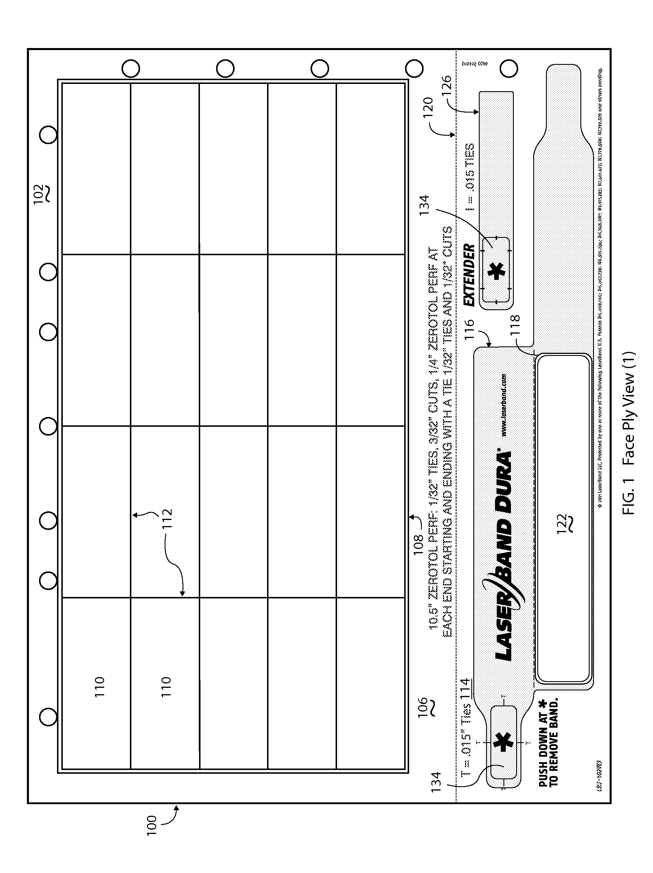
[0022]In the first embodiment depicted in FIGS. 1, 3, 4, 5, 7, and 8 the wristband 116 includes a laminating portion 124 comprised of a pair of different length laminating panels 126, 128, with panel 126 being sized to merely overlap and laminate the imaging area 122 after separation of the wristband 116. By “merely laminate” is meant that the panel 126 is sufficient to approximate the dimensions of the imaging area 112, and preferably although not absolutely necessarily slightly larger in each dimension so as to form a window frame pattern completely surrounding and encapsulating the imaging area 112 when laminated. An integrally formed, adhesive coated tab 130 extends from opposing ends of the two laminating panels 126, 128 which are used to apply the wristband 116 to a patient's wrist or other appropriate extremity. The extended length of laminating panel 128 effectively forms a strap 129 which bridges the laminated imaging area 112 to the associated tab 130. Preferably, a fold l...

second embodiment

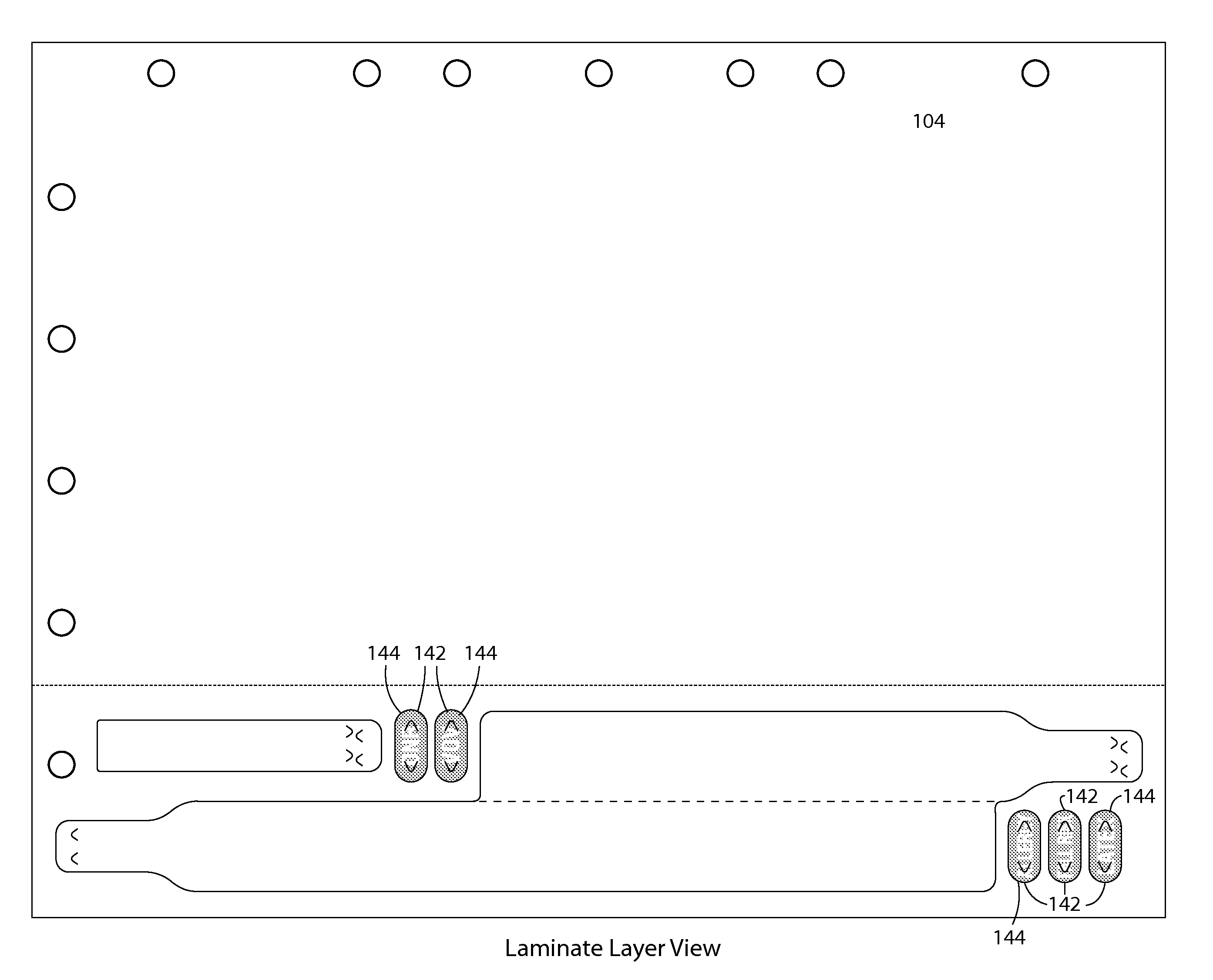
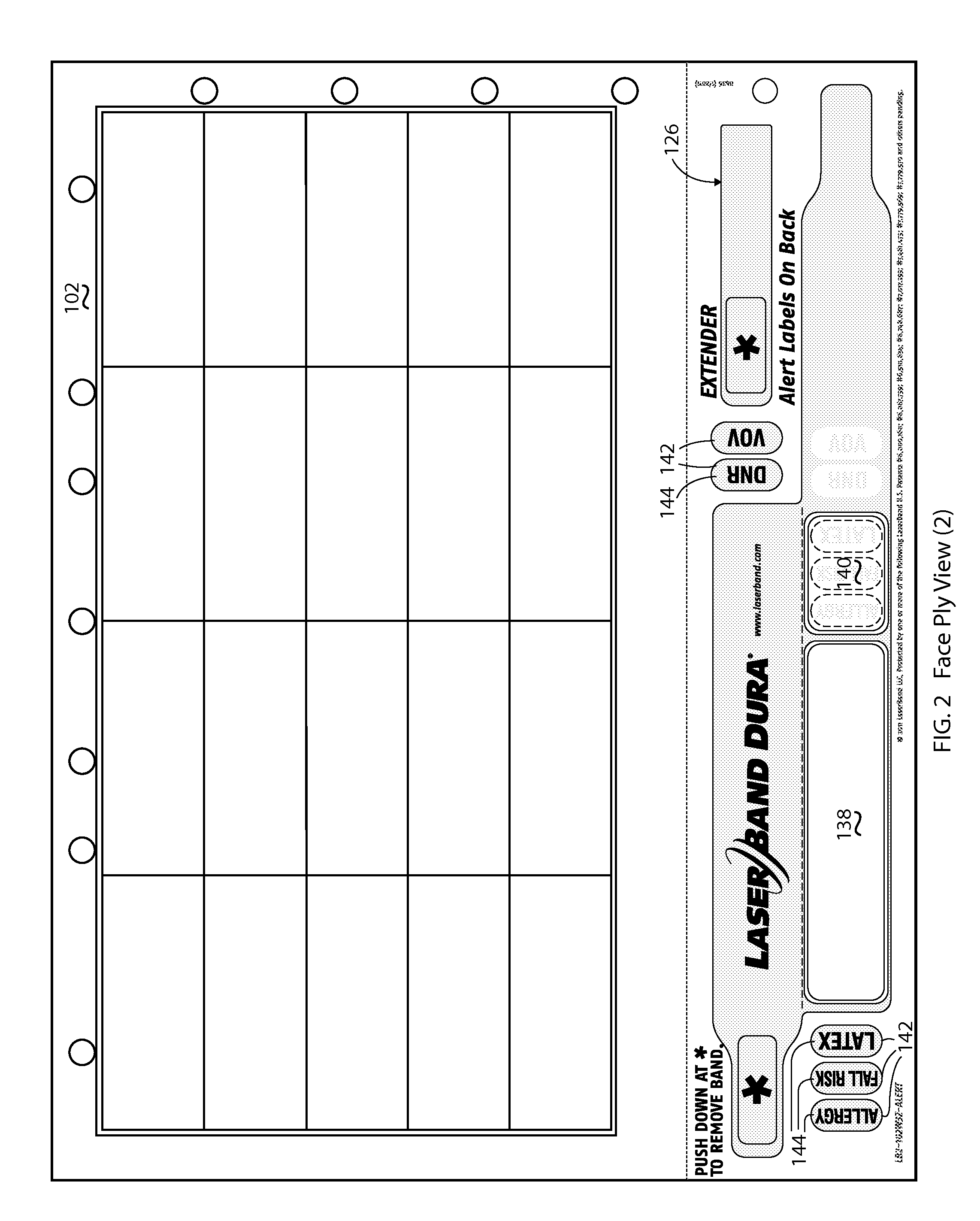
[0026]FIGS. 2 & 6 depict a second embodiment including a pair of separated imaging areas 138, 140 with the left imaging area 138 providing space for printing the usual patient / Doctor information and the right imaging area 140 providing space for one or more special precautions labels 142 to be adhered. These special precautions labels 142 are defined by die cuts 144 in the laminate ply 104 and may be separated therefrom and applied to the imaging area 138 after separation of the wristband 116 from the business form 102 and before lamination so that they become virtually permanently affixed and resistant to tampering. These special precautions labels 140 may be color coded to help attract the attention of health care professionals as they treat the patient. Also, another set of die cuts 146 may be applied to the tabs 130 to make them tamper evident should a patient remove his / her wristband and reapply it without authority, such as when patients might seek to swap wristbands.


PUM


Abstract

A business form comprising a face ply and a lamination ply includes a matrix of self adhering labels positioned in a label area and a self laminating wristband positioned in a wristband area, all of which are defined by die cuts therein for removal upon use. The wristband is comprised of a left edge justified, reduced length imaging area releasably adhered to a laminating portion comprising a pair of laminating panels one of which is smaller sized to merely laminate the imaging area and with self adhering tabs at opposite ends of the panels. A wristband extender is die cut into the lamination ply within the profile of the wristband. A second embodiment includes a pair of separated imaging areas in the same space as the single imaging area along with special precautions labels die cut into the lamination ply for application to the second smaller imaging area. The wristband may be provided separately in an envelope sized sheetlet or in a page size form with multiple wristbands but no labels.

Description

BACKGROUND AND SUMMARY OF THE INVENTION[0001]Self laminating wristbands of various inventive designs have been made and sold, and achieved immense commercial success, by the assignee of the present invention. Many of these have been patented by the assignee including those covered by one or more of U.S. Pat. Nos. 6,000,160, 6,748,687, 7,047,682, 7,017,293, 7,654,024, 7,763,344, 7,779,569, and others of record assigned to the assignee hereof, the disclosures of which are incorporated herein by reference. In its continuing efforts to develop improved wristbands to meet the varying needs of its customers and users, the inventors herein have succeeded in designing and inventing a new self laminating wristband which incorporates many of the same advantages of previous designs but which also provides significant new advantages and features.[0002]Perhaps the first of the assignee's patented wristbands includes a full length image or imaging area adhered to one of a pair of aligned, full le...

Claims


Application Information

Patent Timeline
IPC IPC(8): G09F3/10A44C5/00
CPCG09F3/005
Inventor JAIN, SANJAY K.GREER, MARK
Owner ZEBRA TECH CORP
Why Eureka
Try Eureka