
Laser wind velocimeter with multiple radiation sources

a technology of laser wind and velocity measurement, applied in the direction of electric generator control, instruments, and using reradiation, can solve the problem of not enabling simultaneous measurements of three components of velocity, and achieve the effect of improving timeliness and accuracy of readings

Active Publication Date: 2013-08-13
RD2 LLC
View PDF28 Cites 24 Cited by
  • Summary
  • Abstract
  • Description
  • Claims
  • Application Information

AI Technical Summary

Benefits of technology

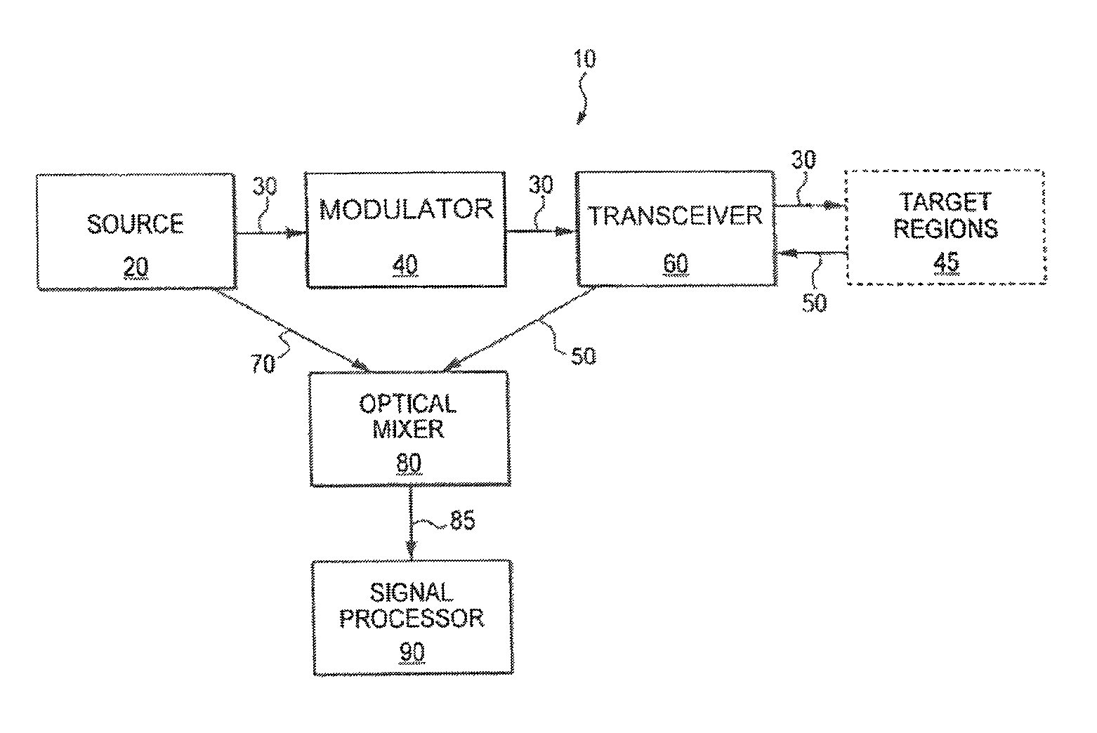
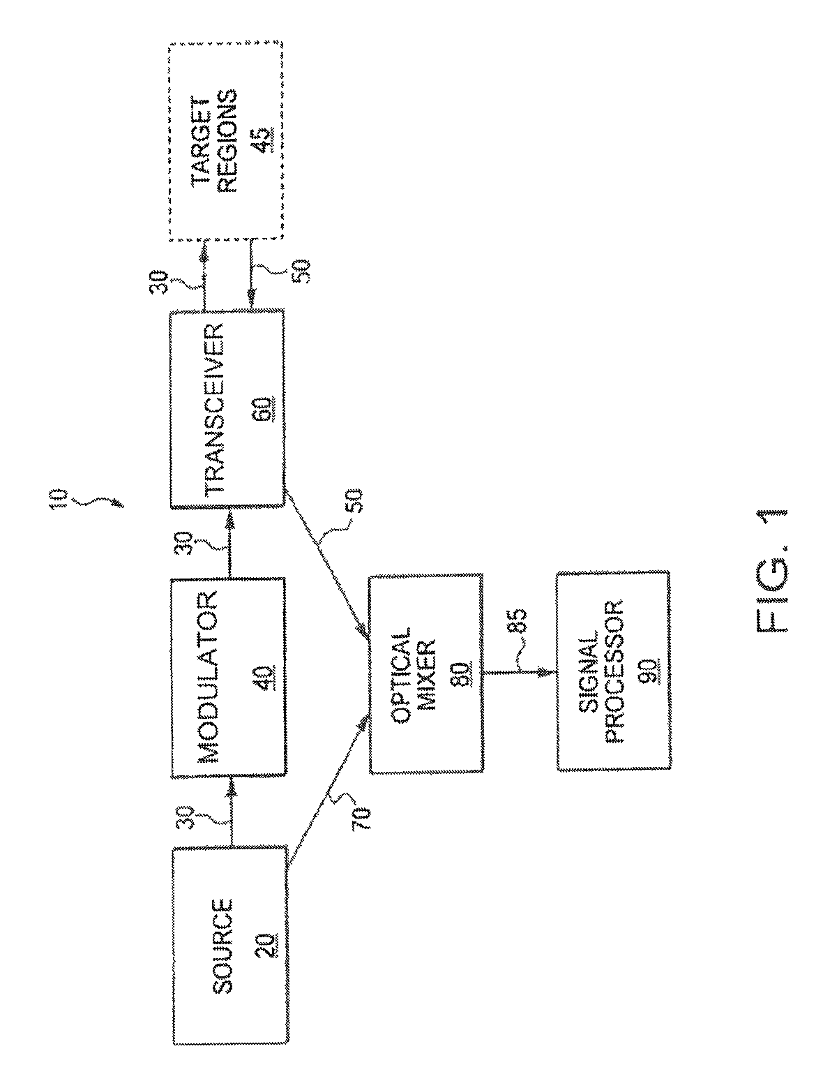
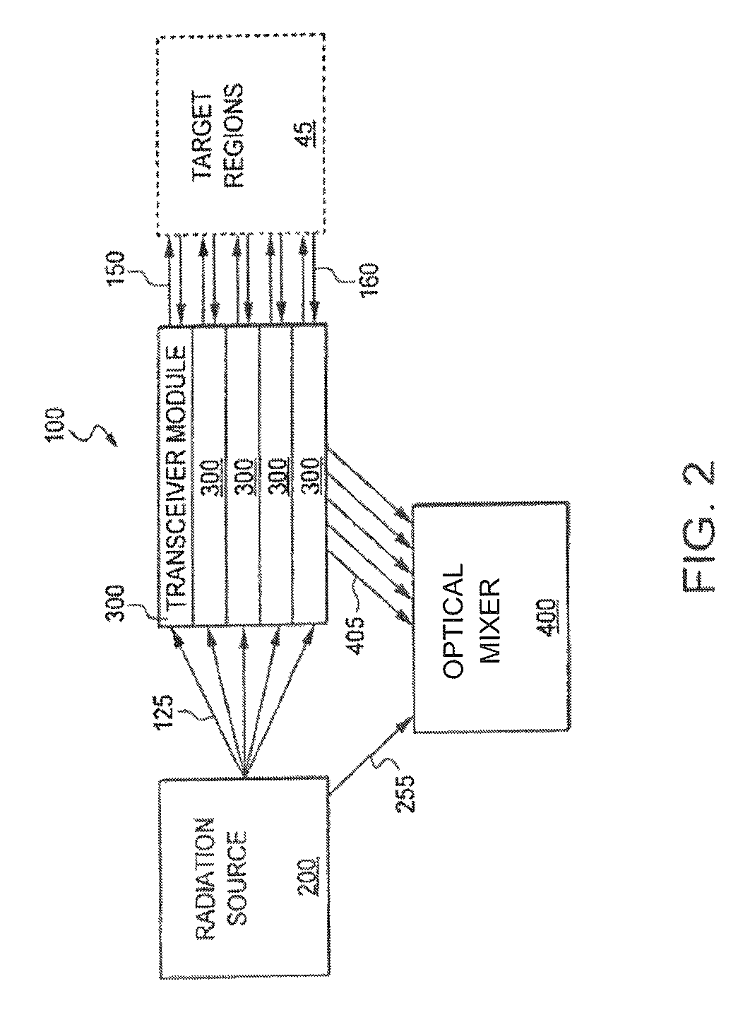
[0005]Therefore, what is needed is an LDV with more than one transceiver, and e.g., three or more transceivers, where all of the transceivers are transmitting a beam of light within a target region or regions substantially simultaneously. Using the plurality of transceivers each aimed at a different area of the target region allows for substantially simultaneous velocity measurements along a plurality of different axes, thus allowing for a multi-dimensional velocity determination. In one example, by simultaneously transmitting light to the different areas of the target regions, the accuracy of the readings is greatly improved while eliminating the need for any moving parts. In another example, the timeliness of the measurements is improved. What is also needed are improvements to LDVs that result in the use of eye-safe radiation sources, e.g., in the 1.4-1.6 micron range.

Problems solved by technology

This approach is disadvantageous in that is does not enable simultaneous measurements of three components of velocity.

Method used


Image

  • Laser wind velocimeter with multiple radiation sources
  • Laser wind velocimeter with multiple radiation sources
  • Laser wind velocimeter with multiple radiation sources

Examples


Embodiment Construction

[0020]This specification discloses one or more embodiments that incorporate the features of this invention. The disclosed embodiment(s) merely exemplify the present invention. The scope of the present invention is not limited to the disclosed embodiment(s). The present invention is defined by the claims appended hereto.

[0021]The embodiment(s) described, and references in the specification to “one embodiment”, “an embodiment”, “an example embodiment”, etc., indicate that the embodiment(s) described may include a particular feature, structure, or characteristic, but every embodiment may not necessarily include the particular feature, structure, or characteristic. Moreover, such phrases are not necessarily referring to the same embodiment. Further, when a particular feature, structure, or characteristic is described in connection with an embodiment, it is understood that it is within the knowledge of one skilled in the art to affect such feature, structure, or characteristic in connect...


PUM


Abstract

A system and method for measuring wind velocities are provided. A laser wind velocimeter with a radiation source includes a fiber laser. All optical signals, transmitted and received, are conveyed by optical fibers. An amplifier amplifies a source laser, which is then transmitted to one or more transceivers. The one or more transceivers, each projecting along a different axis, and each with a single optical fiber input / output interface act as both the transmission device to focus the radiation at a target region, and as the receiving system for collecting reflected radiation. The one or more transceivers transmit radiation to the target region. A portion of the reflected radiation collected by the receiving system is analyzed to determine the Doppler shift, which can me used to measure wind velocity.

Description

FIELD[0001]This disclosure relates to the field of laser based velocity measurement of wind or solid objects.BACKGROUND ART[0002]Conventional laser Doppler velocimeters (“LDVs”) transmit light to a target region (e.g., into the atmosphere) and receive a portion of that light after it has scattered or reflected from the target region or scatterers in the target region. This received light is processed by the LDV to obtain the Doppler frequency shift, fD. The LDV conveys the velocity of the target relative to the LDV, v, by the relationship v=(0.5)cfD / ft where ft is the frequency of the transmitted light, and c is the speed of light in the medium between the LDV and the target.[0003]LDV's are have a wide range of applications including, but not limited to: blood-flow measurements, speed-limit enforcement, spaceship navigation, projectile tracking, and air-speed measurement. In the latter case the target consists of aerosols (resulting in Mie scattering), or the air molecules themselve...

Claims


Application Information

Patent Timeline
Patent Type & Authority Patents(United States)
IPC IPC(8): G01P3/36
CPCG01S17/87G01S17/95G01S7/4815G01S7/4818G01P5/26G01S17/58Y02A90/10
Inventor CHANG, CHIA-CHENMAMIDIPUDI, PRIYAVADANLECLAIR, LANCEGATCHELL, PETERDAKIN, DANIELDAKIN, ELIZABETH A.
Owner RD2 LLC
Learn More