Cascade floating intermediate temperature heat pump system

a heat pump system and intermediate temperature technology, applied in heat pumps, refrigeration components, lighting and heating apparatus, etc., can solve the problems of inefficiency of traditional two-stage cascade systems, inability to efficiently operate compressors, and inability to meet the needs of cold-climate heating applications, and achieve the effect of maximizing the coefficient of system performan

Active Publication Date: 2012-08-23
ROCKY RES INC
View PDF12 Cites 55 Cited by
  • Summary
  • Abstract
  • Description
  • Claims
  • Application Information

AI Technical Summary

Problems solved by technology

Single-stage vapor-compression systems are not practical for cold-climate heating applications due to the low suction pressure of the refrigerant at low ambient temperature and the difficulty of efficiently operating compressors at high compression ratios and compressing refrigerants with large specific volume.
However, these traditional two-stage cascade systems suffer from inherent inefficiencies that result from the overlap of the condensing temperature in the lower stage and the evaporating temperature in the upper stage.

Method used


Image

  • Cascade floating intermediate temperature heat pump system
  • Cascade floating intermediate temperature heat pump system
  • Cascade floating intermediate temperature heat pump system

Examples


working example

Example 1

Computer Simulation

[0048]In order to investigate the energy efficiency benefits of a system as described above, the software “Cycle_D version 4” made by the National Institute of Standards and Technology was used.

[0049]Three cases were investigated: (1) a single-speed, single-stage heat pump using R-410a; (2) a single-speed two-stage cascade heat pump with R-410a in the lower stage and R-134a in the higher stage; and, (3) a variable-speed two-stage CFITHP with R-410a in the lower stage and R-134a in the higher stage. The results are summarized in the table below.

CondenserHeatingPowerEvaporatorTemp. CapacityConsump.HeatingSYSTEMTemp. (° F.)(° F.)(Btu / hr)(kW)COPSingle-Speed−2011060,2007.32.6Single-Stage(R-410a)Single-Speed−2011060,2756.22.85Two-StageCascade (R-410a / R-134a)Variable-−2011060,6505.53.2SpeedTwo-StageCFITHP (R-410a / R-134a)

Computer Simulation Results

[0050]As shown, given the same evaporator temperature, condenser temperature, and substantially the same heating capa...


PUM


Abstract

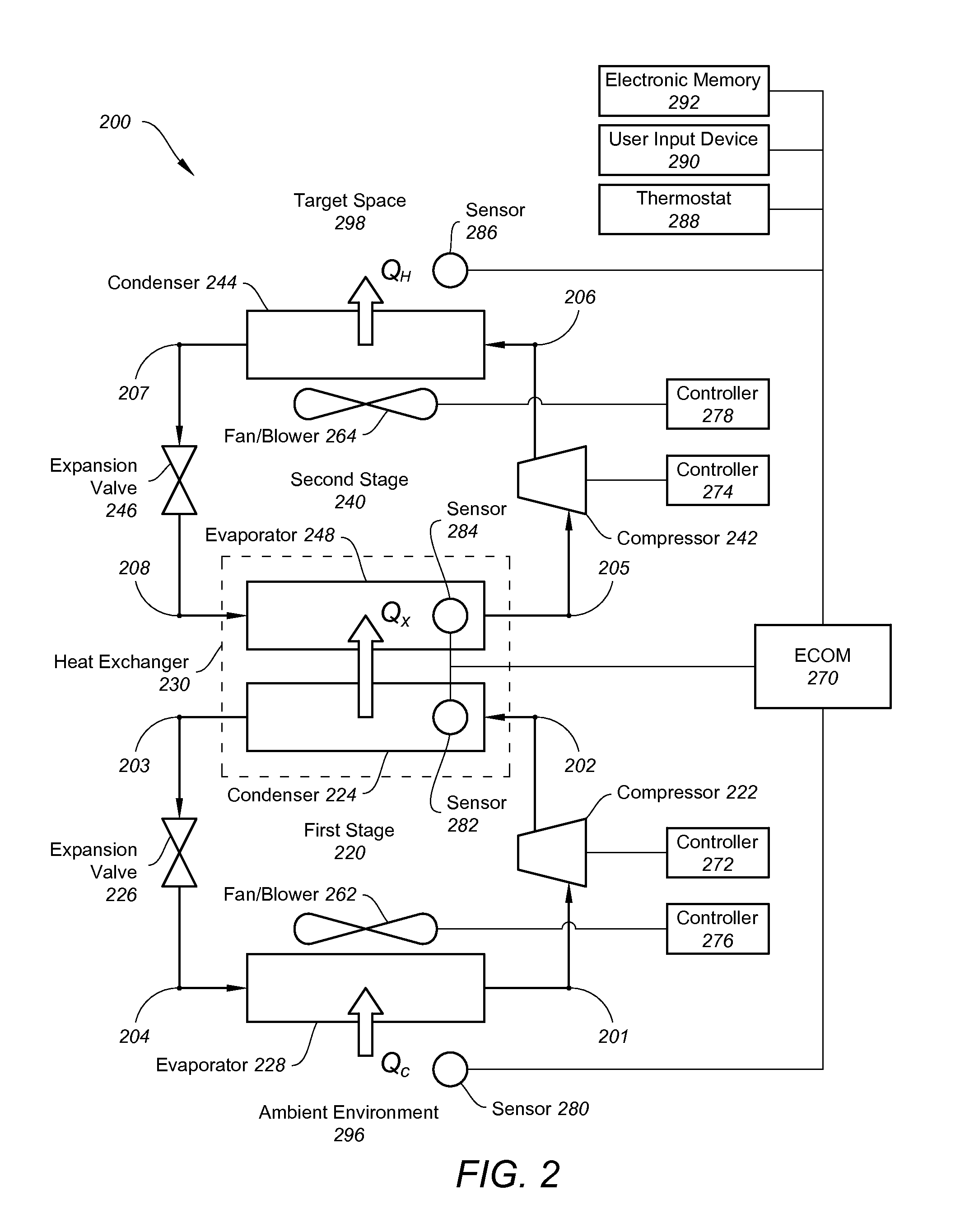
A cascade heat pump system is configured with variable-speed compressors which allow operation at a high system coefficient of performance for a given thermal load. An electronic control module may be utilized to dynamically vary the speed of the compressors to achieve maximum energy efficiency. Variable-speed fans or blowers may also be used.

Description

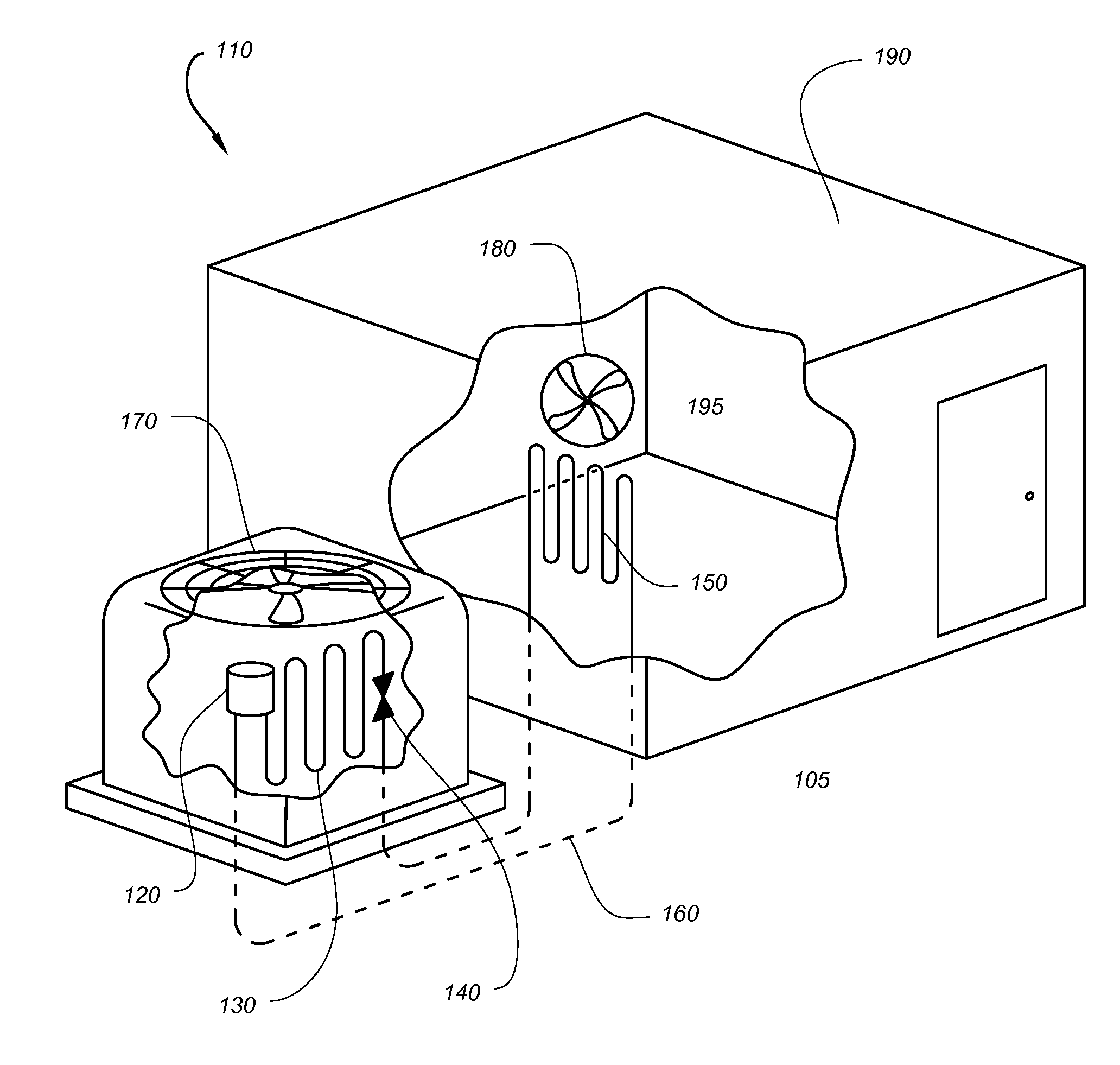
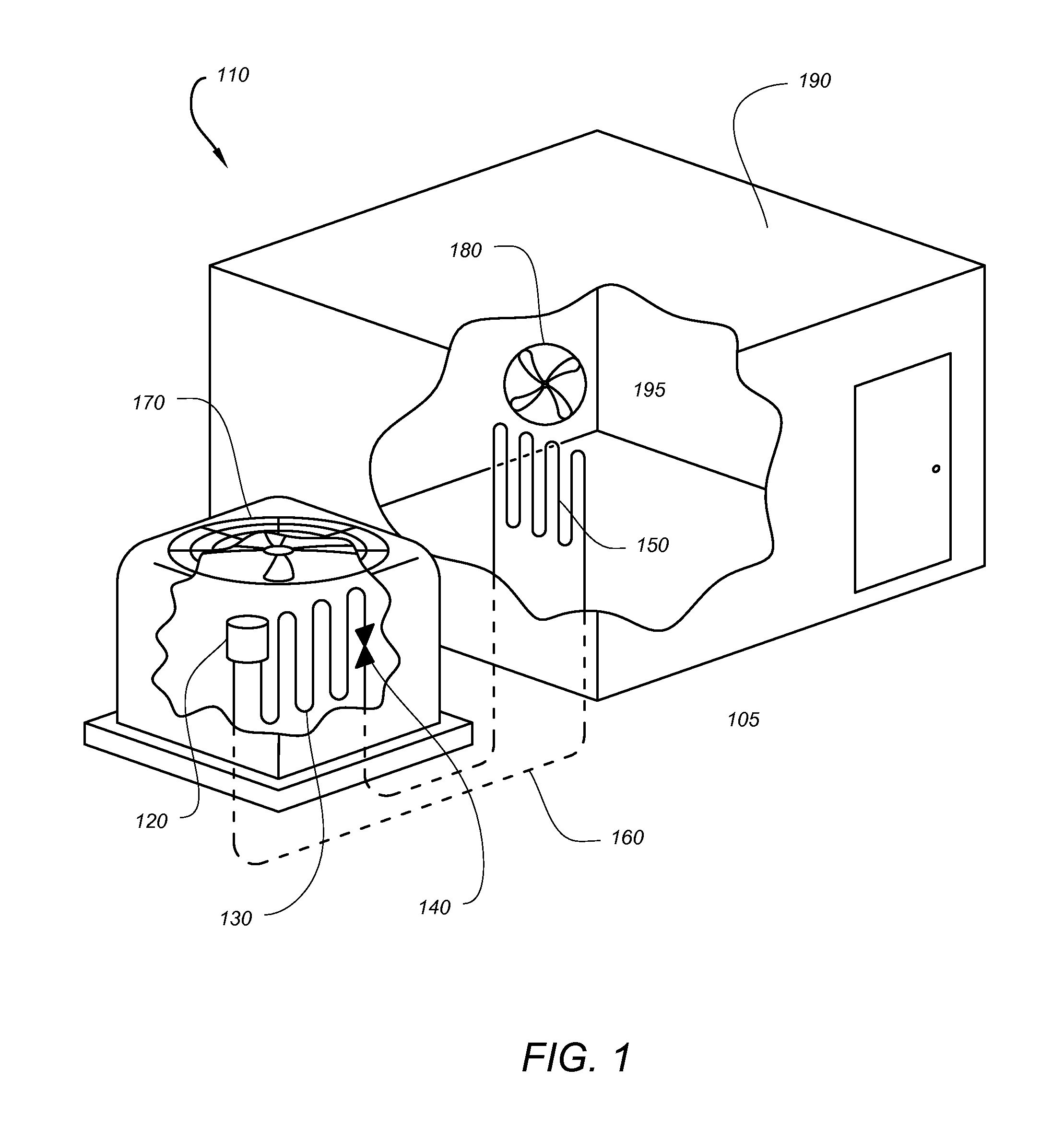
BACKGROUND[0001]Heat pumps are often employed to provide heating or cooling to a target space or zone, often the indoor area of a residential or commercial building. The most common type of heat pump is the air-source heat pump, which transfers and amplifies heat between a target space and the air in another space, often an ambient environment. For heating, ventilation, and air conditioning / refrigeration (HVAC / R) applications, heat pumps often utilize the vapor-compression refrigeration cycle, in which a circulating refrigerant is used as the medium which absorbs heat from one space and subsequently rejects the heat elsewhere.[0002]In a single-stage vapor-compression heat pump system, the refrigerant flows through an evaporator which absorbs heat and produces a vapor and then to a compressor that provides the necessary pressure increase before entering a condenser to reject the heat. The refrigeration is then expanded to a low pressure using an expansion device such as a thermal exp...

Claims


Application Information

Patent Timeline
Patent Type & Authority Applications(United States)
IPC IPC(8): F25B1/00F25B49/02
CPCF25B7/00F25B49/02F25B2600/025F25B2600/111Y02B30/743F25B2700/21151F25B2700/21152F25B2700/21161F25B2700/21171F25B2600/112Y02B30/70F25B30/00
Inventor ROCKENFELLER, UWESARKISIAN, PAULKHALILI, KAVEH
Owner ROCKY RES INC
Why Eureka
Try Eureka