Electroerosion machining systems and methods

a technology of electroerosion machining and machining system, applied in the direction of manufacturing tools, electrolysis components, electrolysis processes, etc., can solve the problems of disadvantageous subsequent electroerosion machining, the machining quality of the workpiece is affected by heat on the workpiece, and the material properties are undesirabl

Inactive Publication Date: 2012-08-23
GENERAL ELECTRIC CO
View PDF3 Cites 15 Cited by
  • Summary
  • Abstract
  • Description
  • Claims
  • Application Information

AI Technical Summary

Benefits of technology

[0006]An electroerosion machining system is provided in accordance with one embodiment of the invention. The electroerosion machining system comprises one or more electrodes configured to machine a workpiece, a power supply configured to energize the workpiece and the respective one or more electrodes, an electrolyte supply configured to pass an electrolyte between the workpiece and the respective one or

Problems solved by technology

However, in some applications, during conventional electroerosion machining, due to insufficient flushing capabilities, the molten chips may interact with the workpiece being machined so as to stick or attach to the workpiece and transfer

Method used


Image

  • Electroerosion machining systems and methods
  • Electroerosion machining systems and methods
  • Electroerosion machining systems and methods

Examples


Embodiment Construction

[0012]Preferred embodiments of the present disclosure will be described hereinbelow with reference to the accompanying drawings. In the following description, well-known functions or constructions are not described in detail to avoid obscuring the disclosure in unnecessary detail.

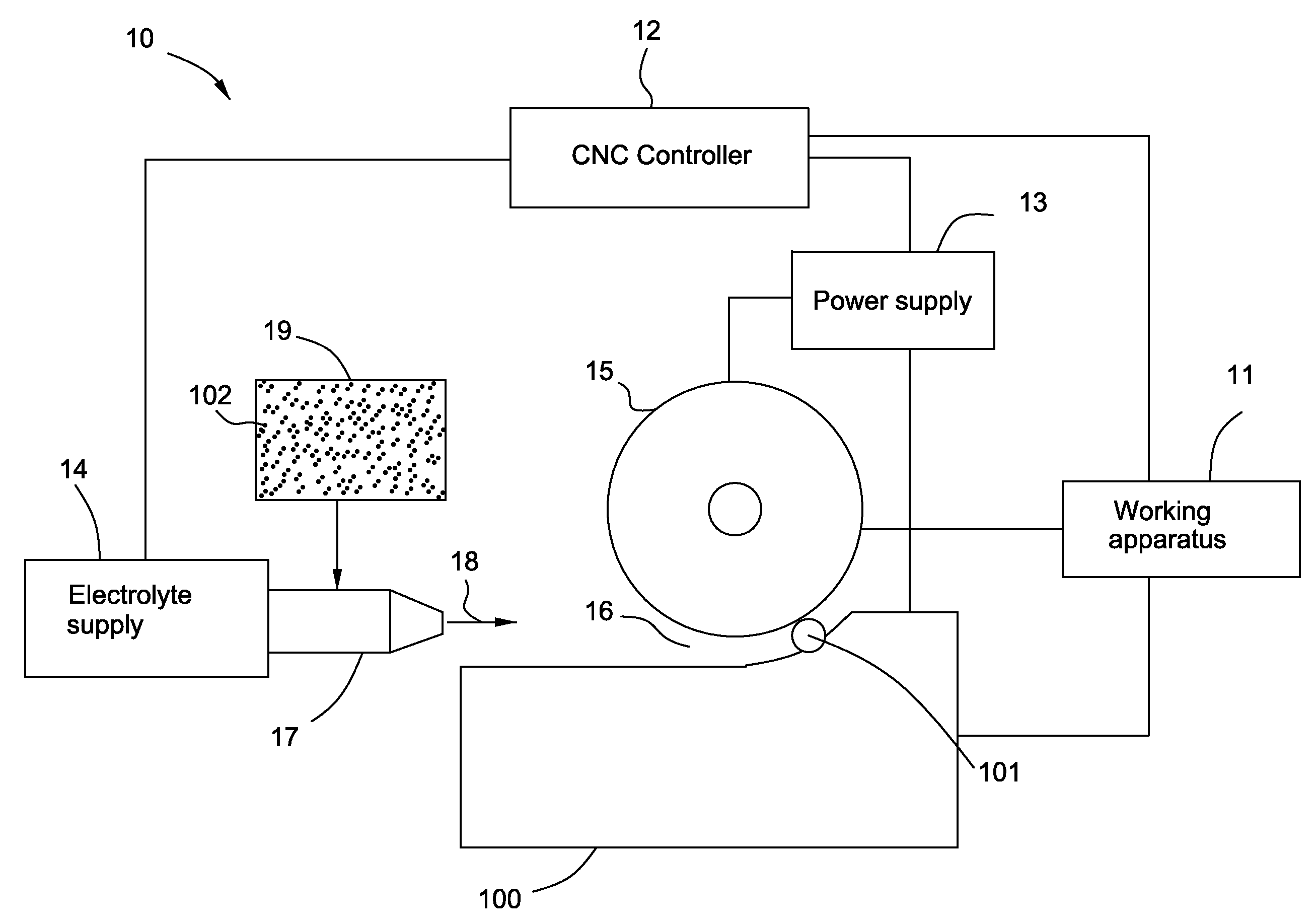
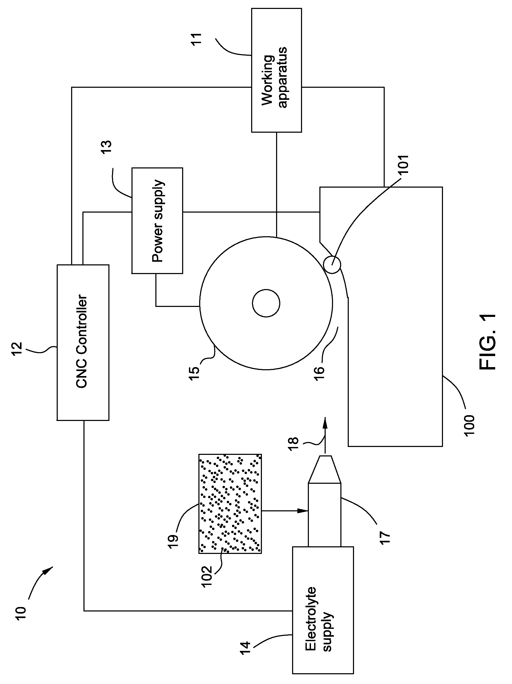
[0013]FIG. 1 illustrates a schematic diagram of an electroerosion machining system 10 in accordance with one embodiment of the invention. In embodiment of the invention, the electroerosion machining system 10 is used to remove material from a workpiece 100, such as titanium alloy layer by layer to form a desired configuration. As illustrated in FIG. 1, the electroerosion machining system 1 comprises a numerical control (NC) or computer numerical control (CNC) device (not shown) including a working apparatus 11 and a controller 12, a power supply 13, an electrolyte supply 14, and an electrode 15. In one non-limiting example, the electroerosion machining system 1 comprises a high speed electroerosion (HSEE) m...


PUM

PropertyMeasurementUnit
Currentaaaaaaaaaa

Abstract

An electroerosion machining system comprises one or more electrodes configured to machine a workpiece, a power supply configured to energize the workpiece and the respective one or more electrodes, an electrolyte supply configured to pass an electrolyte, and a working apparatus configured to move the respective one or more electrodes relative to the workpiece. The electroerosion machining system further comprises a controller configured to control the working apparatus to machine the workpiece, and a removal agent configured to cooperate with the electrolyte from the electrolyte supply for removal of removed material from the workpiece. An electroerosion machining method is also presented.

Description

BACKGROUND[0001]This invention relates generally to electroerosion machining systems and methods. More particularly, this invention relates to electroerosion machining systems and methods with higher flushing capabilities for machining workpieces.[0002]Electrochemical machining (ECM) and electrical discharge machining (EDM) are conventional processes for machining material in objects such as gas turbine components. ECM processes typically pass an electrical current in the gap between an electrode(s) and a workpiece for precision removal of amounts of material on the workpiece to achieve a desired final configuration thereof with substantially smooth surfaces. EDM processes circulate a dielectric liquid between an electrode(s) and a workpiece, and electrical discharges are generated in the gap between the electrode and the workpiece.[0003]Both ECM and EDM processes use electrical current under direct-current (DC) voltage to electrically power removal of the material from the workpiec...

Claims


Application Information

Patent Timeline
IPC IPC(8): C25B9/00
CPCB23H1/08B23H3/08B23H7/34B23H5/12B23H5/06B23H7/12
Inventor TRIMMER, ANDREW LEELUO, YUANFENGWEI, BINCINTULA, MARK JAMES
Owner GENERAL ELECTRIC CO
Why Eureka
Try Eureka