High-power electromagnetic pulse launcher in well

a launcher and electromagnetic pulse technology, applied in the field of control technology and hardware of downhole geophysical measurement, can solve the problems of inconvenient prospecting work, and achieve the effect of improving prospecting accuracy and accuracy

Inactive Publication Date: 2012-08-23
HU WENBAO +14
View PDF4 Cites 7 Cited by
  • Summary
  • Abstract
  • Description
  • Claims
  • Application Information

AI Technical Summary

Benefits of technology

[0008]It is thus an objective of the invention to provide a downhole high power electromagnetic pulse transmitting device, which can realize instantaneous large power pulsed magnetic field excitation in a cased hole and complete full-time data recording of downhole waveform transmission and signal reception so as to provide an observation system for a borehole electromagnetic detection method to evaluate remaining oil distribution in oil reservoir development.
[0024]A method used in the invention is to boost and rectify 220V AC voltage to charge the capacitor, whose power switch discharges to the transmitting coil. Since the capacitor has small internal resistance and large capacity, it can output an instantaneous high current with pulse of hundreds of amperes, which can easily provide a strong power excitation magnetic dipole source due to high energy ratio. Consequently people can understand conductivity changes of the steel casing and find out more oil and natural gas resources. There is no need to wash the well during the work and the probe radius is large. At the time when large instantaneous current is acquired, the average power consumption of the power supply is not so large. As most of the present downhole measuring instruments cannot break through the restriction of the steel casing, they cannot be used in steel-cased hole. But the device used in the invention is able to break through the restriction of the steel casing. Because the average power is small, measuring instrument cables can be connected without any changes so that it reduces the use cost.

Problems solved by technology

However in that age, the increased power is proportional to the volume and weight increased to power supply equipment, for example, power generation equipment of 2000 amp needs two huge trucks to drag, which makes it extremely inconvenient for the prospecting work.

Method used


Image

  • High-power electromagnetic pulse launcher in well
  • High-power electromagnetic pulse launcher in well
  • High-power electromagnetic pulse launcher in well

Examples


Embodiment Construction

[0036]This invention is explained in further detail below with the aid of examples and attached drawings and the embodiments shall not be understood as a restriction of the invention.

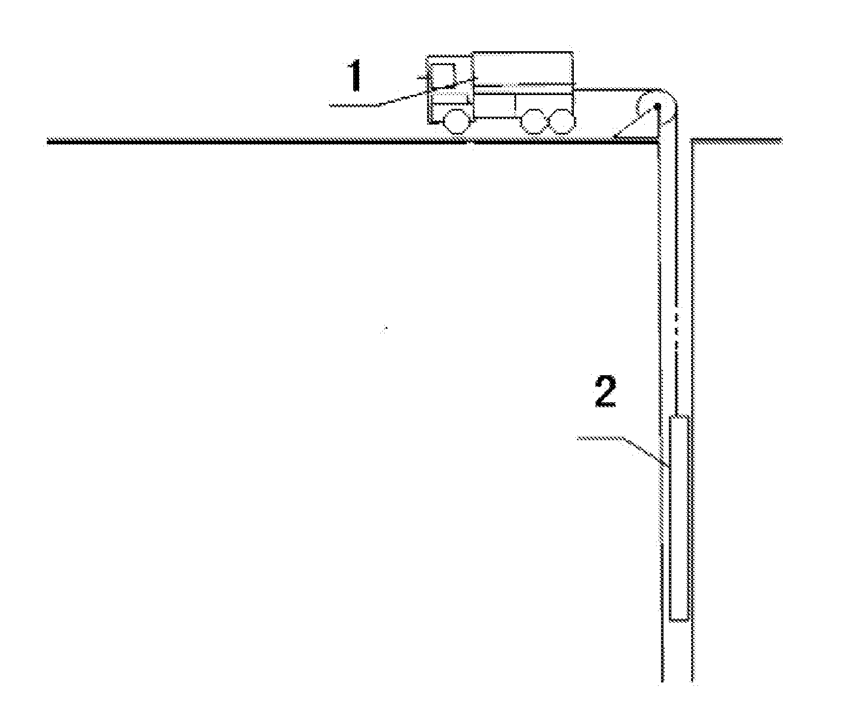
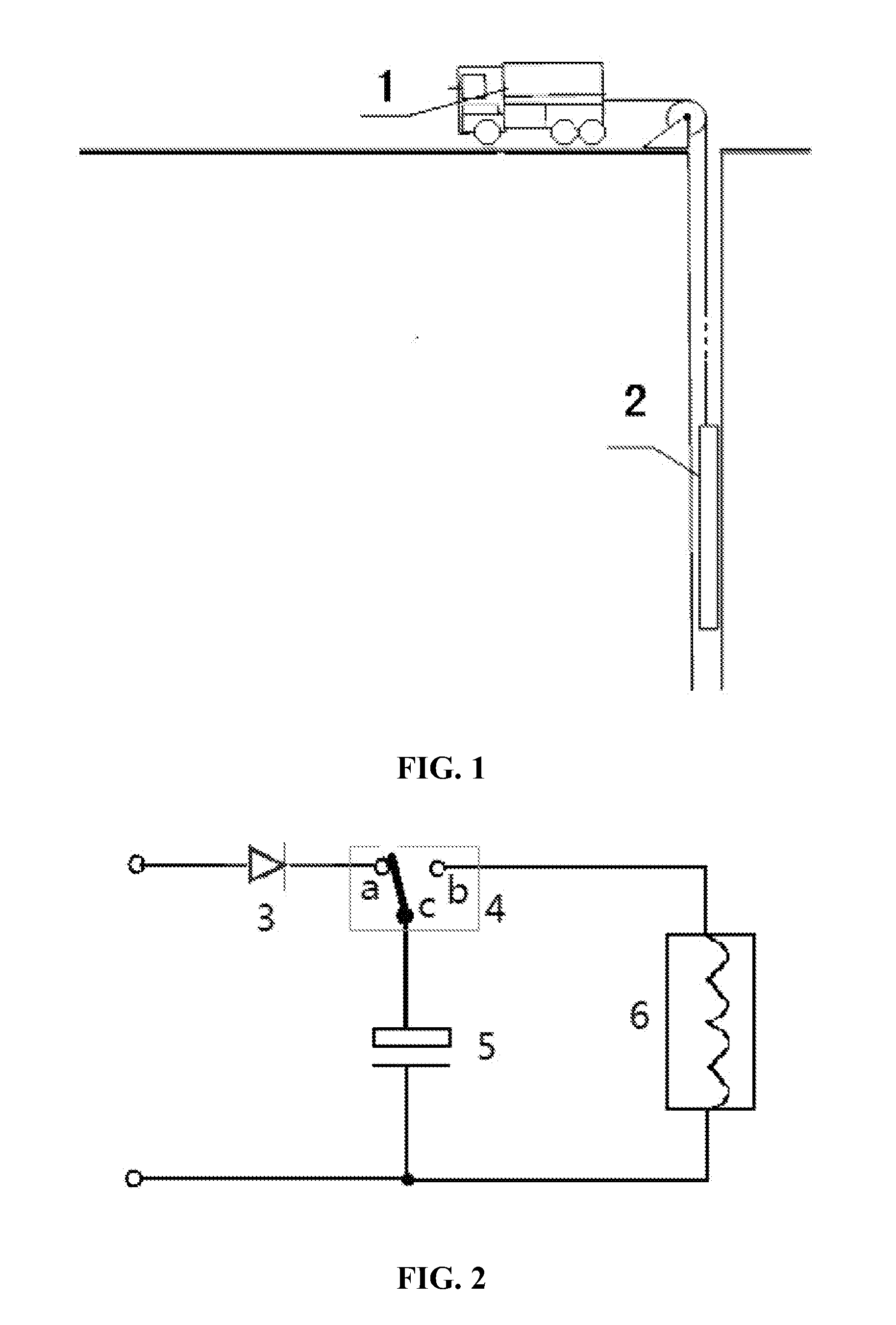
[0037]As shown in FIG. 1, the whole system comprises a ground instrument 1 and a downhole instrument 2. The ground instrument 1 provides power supply and controls the downhole instrument 2.

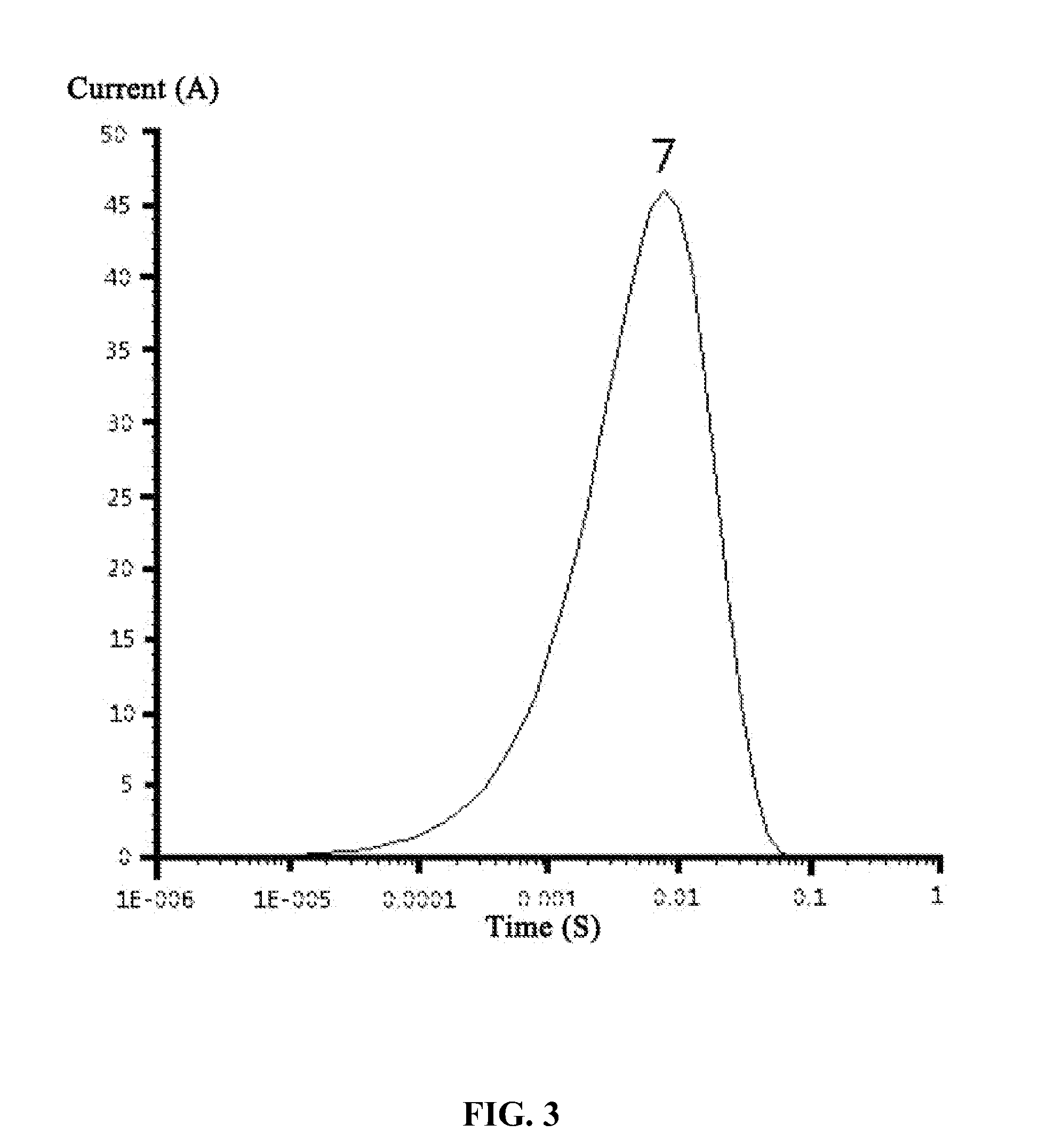
[0038]The downhole high-power electromagnetic pulse transmitting device in accordance with the invention is as shown in FIG. 2. The ground instrument 1 provides AC voltage to charge a capacitor 5 through a rectifier 3 and a switch 4. When charging is complete, the switch 4 disconnects the rectifier 3 and connects to a transmitting coil 6. Thereafter, electric energy (5 is released instantaneously, and a quasi-Gauss pulse waveform 7 is formed as shown in FIG. 3.

[0039]Working procedure of the boosting module is shown in FIG. 4:

[0040]When 220 V / 50 Hz AC voltage passes through a switch 8 and a step-up transformer 9, the v...


PUM


Abstract

A high-power electromagnetic pulse transmitting device for use in a downhole, the device including a ground instrument and a downhole instrument. The ground instrument, with an industrial control computer as the core, includes a depth / magnetic mark / GPS signal recording module, a Manchester coding and decoding module, and a cable drive module, wherein the depth / magnetic mark recording and the Manchester coding and decoding modules communicate respectively through two serial ports with the industrial control computer, and the cable drive module communication for the downhole instrument through four cables by means of phantom power supply. The downhole instrument includes, in turn, from front to rear: an AC voltage boosting module, a rectifier, an energy storage capacitor, a transmitting coil, and a data acquisition module, and further includes a high-voltage discharge switch and a computer-manipulated controller. Power supply of the downhole instrument is provided by the ground instrument through cables.

Description

CROSS-REFERENCE TO RELATED APPLICATIONS[0001]This application is a continuation of International Patent Application No. PCT / CN2011 / 076962 with an international filing date of Jul. 7, 2011, designating the United States, now pending, and further claims priority benefits to Chinese Patent Application No. 201110039340.1 filed Feb. 17, 2011. The contents of all of the aforementioned applications, including any intervening amendments thereto, are incorporated herein by reference.BACKGROUND OF THE INVENTION[0002]1. Field of the Invention[0003]The invention relates to control technology and hardware of downhole geophysical measurement, and more particularly to a device to realize instantaneous large power pulsed magnetic field excitation in a cased hole and observe and measure changes of induced electromotive force using a borehole electromagnetic detection method to evaluate remaining oil distribution in oil reservoir development.[0004]2. Description of the Related Art[0005]One way to ach...

Claims


Application Information

Patent Timeline
Patent Type & Authority Applications(United States)
IPC IPC(8): G01V3/00
CPCG01V3/24
Inventor HU, WENBAOWANG, JUNMINLUO, MINGZHANGZHANG, HUIXU, FEIYANG, XUHUIWEI, YONGLEI, MINGDONG, HAOBINYAN, LIANGJUNXIONG, XIAODONGHU, JIAHUAYANG, JUPENGWANG, LINSONGFU, YONGQIAN
Owner HU WENBAO
Why Eureka
Try Eureka