Apparatus and method for heating a blast furnace stove

a blast furnace stove and stove body technology, applied in the field of blast furnace stove heating methods, can solve the problems of increasing the overall emissions of carbon dioxide from the plant, high flame temperature of the peak flame, and approaching the limits of thermodynamic efficiency

Active Publication Date: 2012-08-23
LINDE AG
View PDF47 Cites 7 Cited by
  • Summary
  • Abstract
  • Description
  • Claims
  • Application Information

AI Technical Summary

Benefits of technology

[0009]The present embodiments solve the above described problems and make it possible to achieve other advantages as will be described below.
[0010]Thus, the present embodiments relate to a method for heating a blast furnace stove by combusting a fuel with a lower heating value (LHV) of 9 MJ / Nm3 or less in a combustion region in which there is maintained a stable visible flame, arranged in a combustion chamber in the stove, and causing the combustion gases to flow through and thereby heat refractory material in the stove, and is characterized in that the fuel is combusted with an oxidant comprising at least 85% oxygen, and in that combustion gases are caused to be recirculated into the combustion region to dilute the mixture of fuel and oxidant therein sufficiently for the flame not to damage the refactory material.

Problems solved by technology

The combustion of such additional fuel leads to larger overall emissions of carbon dioxide from the plant, and is therefore not desirable.
Such methods may in some cases render peak flame temperatures high enough to damage the refractory material of the stove.
It is approaching the limits of thermodynamic efficiency.
Furthermore, the energy consumed in iron making is the dominant factor determining the carbon consumption of the integrated steel making process, and therefore the emissions of carbon dioxide.
In addition to the problem of high peak temperatures mentioned above, too low flame temperatures or heat input rates will lead to long heating cycles, which is undesirable.

Method used


Image

  • Apparatus and method for heating a blast furnace stove
  • Apparatus and method for heating a blast furnace stove
  • Apparatus and method for heating a blast furnace stove

Examples


Embodiment Construction

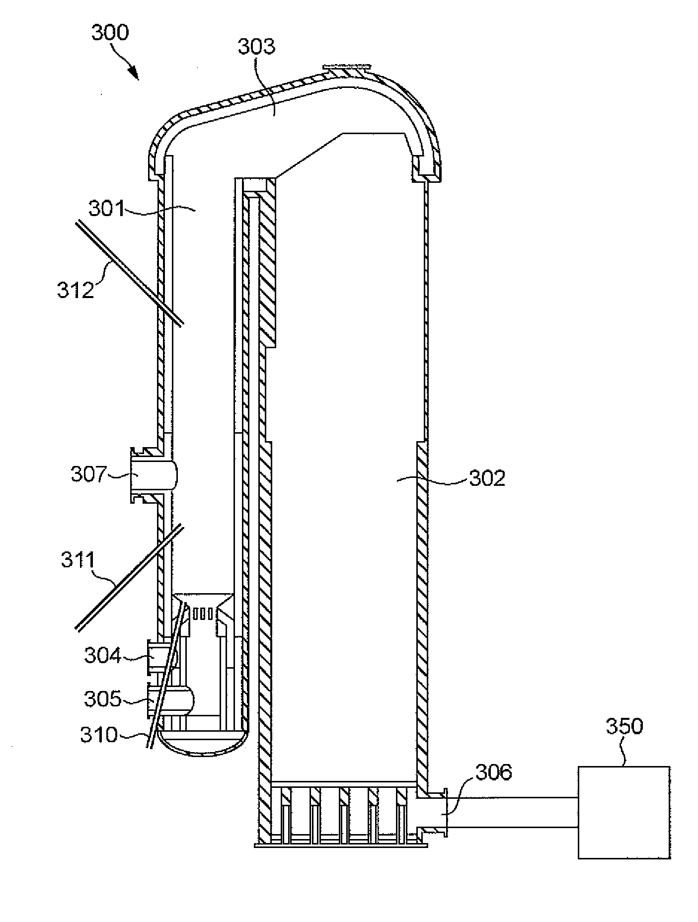
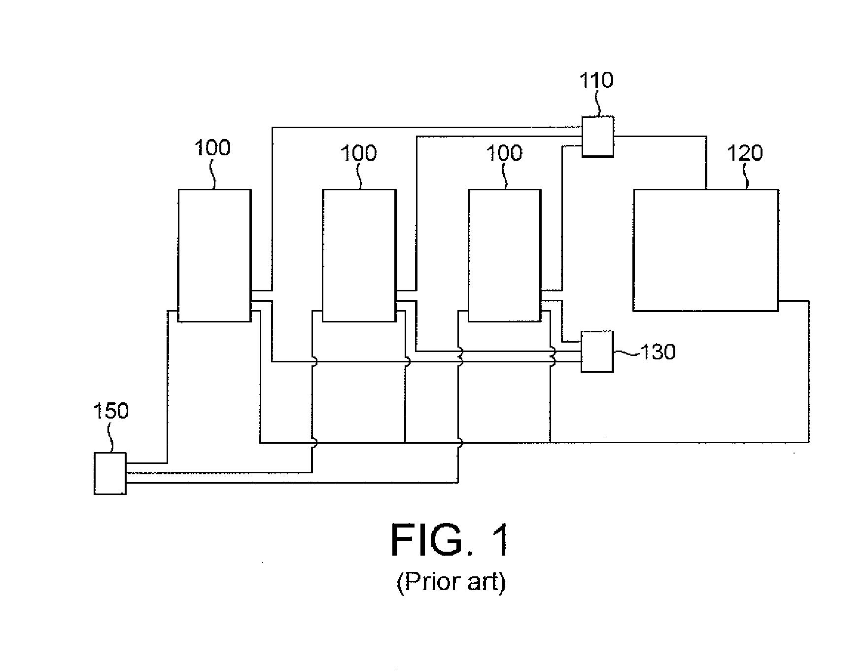
[0022]FIG. 1 illustrates the principal arrangement of a blast furnace 120 and three stoves 100 in an iron works. The operation of the blast furnace 120 produces blast furnace top gas or “top gas”, which is fed, using a fuel supply control device 110, to each stove 100 to be used as fuel to heat the stove 100 in question. The top gas is combusted with an oxidant in the form of air, which is supplied by an air supply control device 130.

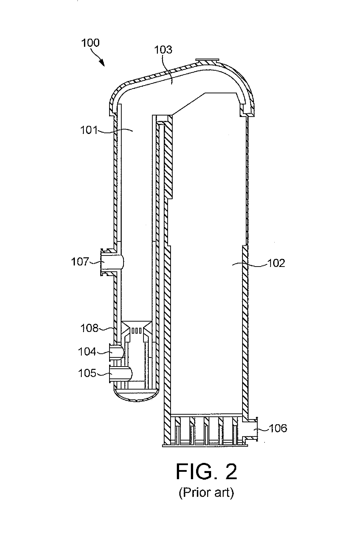
[0023]Each stove 100 comprises refractory material in the form of ceramic bricks or the like, which is first heated and then used to heat blast air which is fed into the blast furnace.

[0024]When operated in refractory material heating mode (“on gas” mode), the top gas is combusted in the stove 100 with the oxidant, and the combustion gases are fed to a flue gas treatment device 150, possibly including a conventional carbon capture step.

[0025]When operated in blast air heating mode (“on blast” mode), air is led through the refractory material in the oppo...


PUM

PropertyMeasurementUnit
temperatureaaaaaaaaaa
velocityaaaaaaaaaa
temperatureaaaaaaaaaa

Abstract

A method for heating a blast furnace stove includes combusting fuel in a combustion chamber in the stove, providing combustion gases from the combustion chamber to heat refractory material in the stove, recirculating exhausted combustion gases into the combustion chamber, enriching the combustion chamber with oxygen sufficient for maintaining combustion in the combustion chamber without damaging the refractory material in the stove.

Description

BACKGROUND[0001]The present invention relates to a method for heating a blast furnace stove for use with a blast furnace.[0002]The combustion air supplied to a blast furnace is typically preheated using a stove, comprising refractory material which is heated using a burner. When the material is hot enough, combustion air is passed through the stoves to pre-heat it before injection into the blast furnace. Usually, several stoves are operated in parallel and cyclically so that at least one stove is operated for heating combustion air while the refractory material of at least one stove is heated.[0003]Conventionally, the top gas leaving the blast furnace has a temperature of around 110-120° C. and contains about 20-25% each of CO and CO2. Typically, 3-5% H2 and some H2O will also be present, but the other major constituent of the top gas is N2 (typically 45-57%). The gas constitutes a low grade fuel, having a relatively low heating value, and is commonly used to fuel the stoves.[0004]T...

Claims


Application Information

Patent Timeline
Patent Type & Authority Applications(United States)
IPC IPC(8): C21B9/14F23G7/06C21B9/02
CPCC21B9/00C21B9/10C21B9/04Y02P10/122C21B5/06C21B9/02
Inventor CAMERON, ANDREW M.RICHARDSON, ANDREW P.
Owner LINDE AG
Why Eureka
Try Eureka