
Squirrel-cage rotor for induction motor

a technology of induction motor and rotor, which is applied in the direction of synchronous motors, dynamo-electric machines, electrical apparatus, etc., can solve the problems of reducing the strength of the rotor, requiring high power and low-calorific power, and difficult to adopt die-casting in the formation of the rotor's conductor parts from metal, such as copper or copper alloy

Active Publication Date: 2012-08-30
FANUC LTD
View PDF7 Cites 13 Cited by
  • Summary
  • Abstract
  • Description
  • Claims
  • Application Information

AI Technical Summary

Benefits of technology

[0012]Under such a situation, an object of the present invention is to provide a squirrel-cage rotor for an induction motor, which can be manufactured by any manufacturing method but die-casting and which allows end rings to be reinforced with use of easily-available material and also allows the junction condition between the bars and the end rings to be confirmed from the outside easily.

Problems solved by technology

However, in recent years, an induction motor generating high power and low-calorific power has been required.
For this reason, it is difficult to adopt die-casting in forming the rotor's conductor part from metal, such as copper or copper alloy.
However, to produce an increase in temperature up to about 800° C. at brazing causes the metal to be annealed to lower its strength.
Thus, there is a possibility that if rotating a motor containing the so-produced rotor at high speed, the holes of the end rings are deformed due to centrifugal force, causing the rotor to be damaged.
However, as the technique disclosed in Japanese Patent No. 2911315 assumes that the bars and the end rings are integrally formed in one body by “aluminum” die-casting, the technique of Japanese patent No. 2911315 cannot be employed in case of forming the bars and the end ring independently of each other.
Japanese Unexamined Patent Application Publication Nos. 10-127022 and 3-261354 and also Japanese Patent No. 2838896 have a common problem that the junction condition between the bars and the end ring is cannot be easily seen from the outside.
Therefore, the method in Japanese Unexamined Patent Application Publication No. 2-119557 accompanies an increased number of manufacturing steps to cause a manufacturing cost to increase.
Further, if the area of each slot gets larger in Japanese Unexamined Patent Application Publication No. 2011-10498, then the reliability of the resultant rotor of Japanese Unexamined Patent Application Publication No. 2011-10498 is not always improved since a wall thickness between the slots and the outer diameter of the rotor is reduced.

Method used


Image

  • Squirrel-cage rotor for induction motor
  • Squirrel-cage rotor for induction motor
  • Squirrel-cage rotor for induction motor

Examples


first embodiment

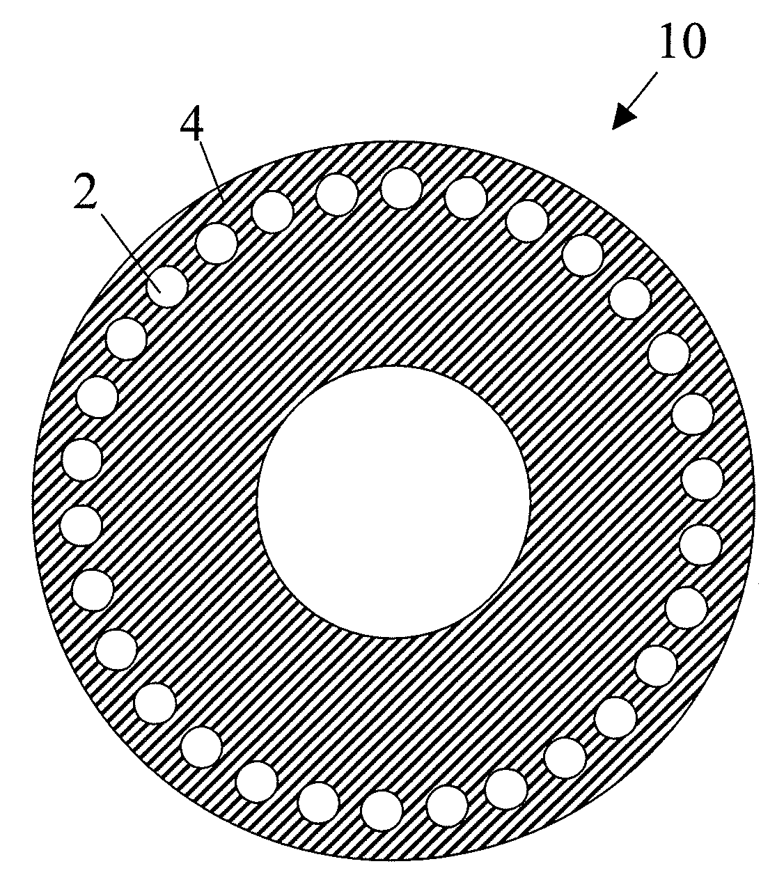
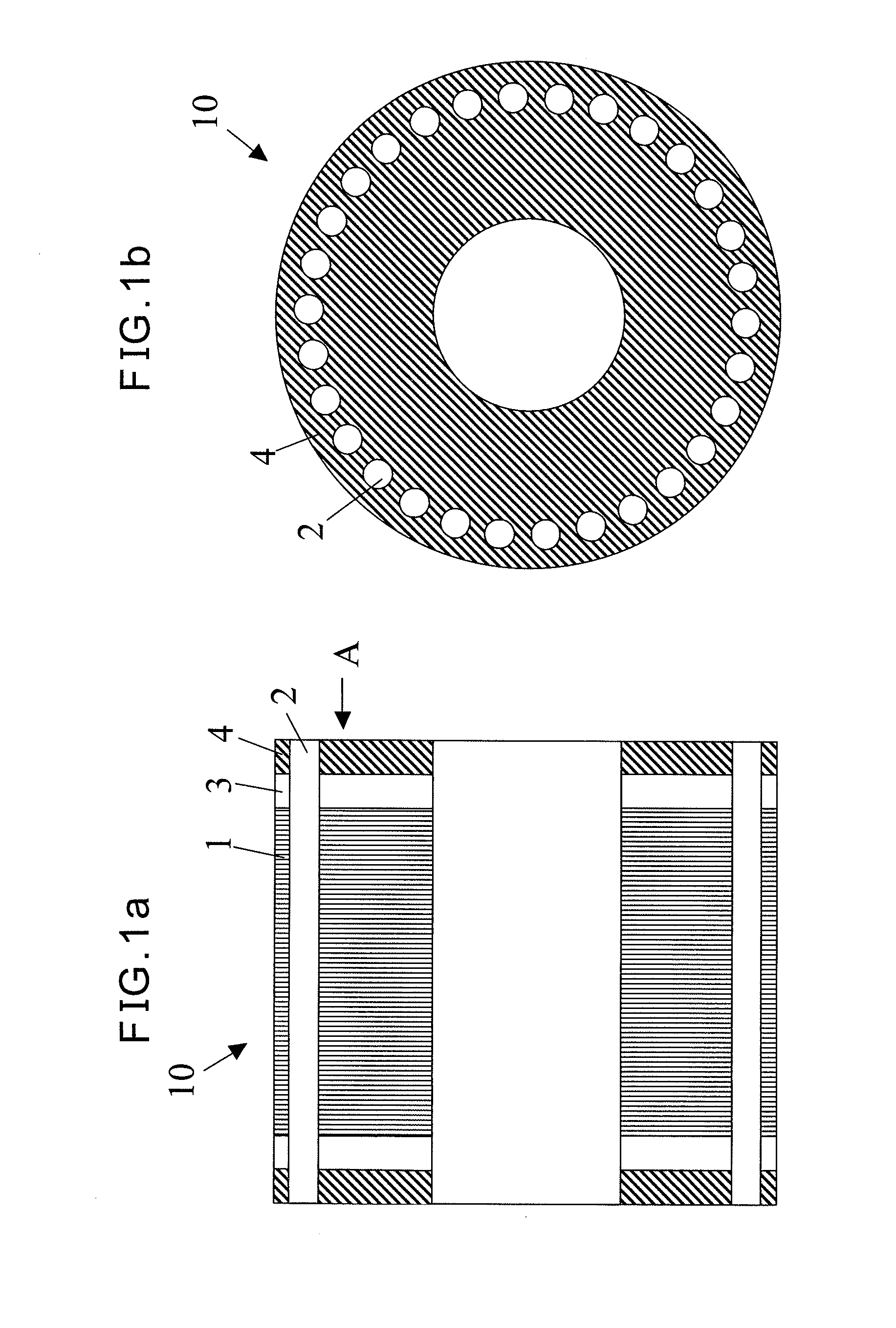
[0027]FIG. 1a is a sectional side view of a squirrel-cage rotor in accordance with the present invention, while FIG. 1b is an end elevation view of the squirrel-cage rotor, viewed along an arrow A of FIG. 1a. The squirrel-cage rotor 10 shown in FIG. 1a comprises a rotor core 1. The rotor core 1 is formed by a normal material for a core of the squirrel-cage rotor 10, for example, a laminated body composed of magnetic steel sheets. The rotor core 1 has a plurality of slots (not shown) formed so as to extend in the axial direction thereof.

[0028]Conductor bars 2 made of copper or copper alloy are inserted into these slots, respectively. The conductor bars 2 have contours generally identical to the shapes of the slots, respectively. As shown in FIG. 1a, each of the conductor bars 2 is longer than the rotor core 1, so that both ends of each bar project from respective end faces of the rotor core 1, respectively.

[0029]As can be seen from FIG. 1b, according to one embodiment, thirty pieces ...

second embodiment

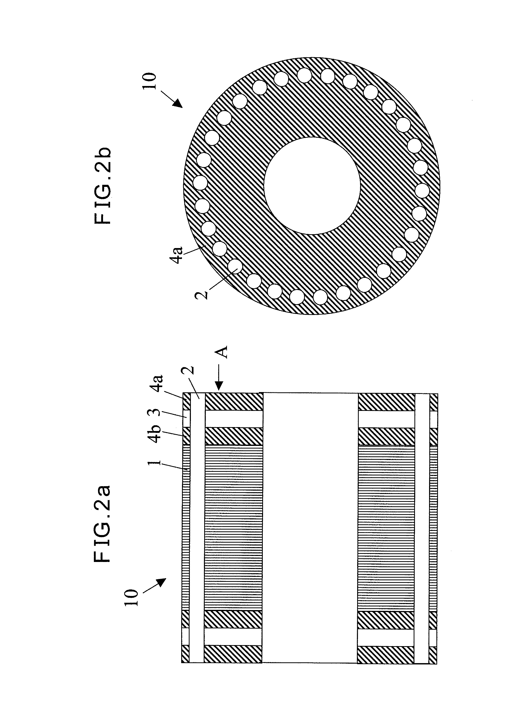
[0039]Thus, the conductor end ring 3 is sandwiched, from both sides thereof, between the first reinforcing-member end ring 4a and the second reinforcing-member end ring 4b. As shown in FIG. 2b, the first reinforcing-member end ring 4a is positioned outside the conductor end ring 3, while the second reinforcing-member end ring 4b is brought into contact with the rotor core 1.

[0040]Further, as shown in FIG. 2a, the respective conductor bars 2 penetrate through corresponding holes (not shown) of both the second reinforcing-member end ring 4b and the conductor end ring 3 and reach up to an outside end of the first reinforcing-member end ring 4a. As can be seen from the figure, respective end faces of the conductor bars 2 are generally in the same planes with the first reinforcing-member end rings 4a. However, both ends of each conductor bar 2 may project from the first reinforcing-member end rings 4a.

[0041]In the second embodiment, the conductor end ring 3 is sandwiched between the re...


PUM


Abstract

A squirrel-cage rotor includes a rotor core formed having a plurality of slots, a plurality of conductor bars inserted into the slots respectively and made of copper or copper alloy, two conductor end rings joined to the plurality of conductor bars on both end faces of the rotor core and made of copper or copper alloy and a reinforcing-member end ring attached to at least one of the conductor end rings and made of material having a specific strength greater than that of either copper or copper alloy. The plurality of conductor bars are arranged so as to extend through the conductor end rings and the reinforcing-member end ring. Consequently, the rotor can be manufactured by any manufacturing method but die-casting. Further, the conductor end rings can be reinforced with an easily-obtainable material and additionally, the junction of conductor end rings can be easily viewed from an outside.

Description

BACKGROUND OF THE INVENTION[0001]1. Field of the Invention[0002]The present invention relates to a squirrel-cage rotor for an induction motor.[0003]2. Description of the Related Art[0004]A squirrel-cage rotor for an induction motor mainly includes a rotor core, a plurality of bars inserted into slots in the rotor core and end rings joined to the bars at both end faces of the rotor core. In views of manufacturing cost and material cost, the plurality of bars and the end rings are frequently made of aluminum, in one body by die cast molding.[0005]However, in recent years, an induction motor generating high power and low-calorific power has been required. For this purpose, a conductor part of the rotor of the induction motor may be made of metal of which resistance is lower than that of aluminum, for example, copper or copper alloy.[0006]Additionally, it is required to speed up the operation of a motor. Nevertheless, since copper or copper alloy has a melting point higher than the melt...

Claims


Application Information

Patent Timeline
IPC IPC(8): H02K17/16
CPCH02K17/16
Inventor KAJIYA, TAKAFUMIMAEDA, HISASHIFUKUDA, MASAMOTO
Owner FANUC LTD
Learn More