Position controller for removable optical element

a technology of optical elements and controllers, which is applied in the field of positioning controllers for removable optical elements, can solve the problems of increasing the size of requiring much time and trouble to adjust to the removal drive mechanism, and maintaining a compact structure, so as to achieve high precision. the effect o

Inactive Publication Date: 2012-08-30
HOYA CORP
View PDF3 Cites 23 Cited by
  • Summary
  • Abstract
  • Description
  • Claims
  • Application Information

AI Technical Summary

Benefits of technology

[0010]The present invention has been devised in view of the above-mentioned drawbacks and provides a position controller for a removal optical element which is moved onto and removed from a photographing optical axis in accordance with switching between a ready-to-photograph state and an accommodated state, wherein the position controller is capable of allowing the removable optical element removing operation to be performed efficiently and with high precision while maintaining a compact structure.
[0014]It is desirable for the position controller to include a positional adjustment mechanism which enables a positional adjustment to be carried out on the removable optical element holding member along a plane orthogonal to the optical axis relative to the advancing / retracting ring independently of rotation of the removable optical element holding member between the insertion position and the removed position.
[0015]It is desirable for the positional adjustment mechanism to include an anti-shake moving member supported by the advancing / retracting ring to be movable along a plane orthogonal to the optical axis; and an anti-shake driver which drives the anti-shake moving member in accordance with vibrations applied to the photographing optical system to reduce image shake of an image focused on an image plane, wherein the removable optical element holding member is pivotally supported on the anti-shake moving member.
[0016]It is desirable for a clearance to be formed between the removable optical element holding member and the removal drive member to prevent interference between the removable optical element holding member and the removal drive member which may be caused by a variation in position of the removable optical element holding member when the photographing optical system is in the ready-to-photograph state, the variation being caused by the positional adjustment mechanism.
[0021]According to the present invention, since the removable optical element holding member is made to rotate to the removed position via the removal drive member, which is a rotational member supported by the advancing / retracting member separately from the removable optical element holding member, a high-precision and reliable removable optical element removing operation can be performed by translating a moving force of the advancing / retracting member into a rotational operation of the removal drive member. In addition, since the positions of the rotational axes of the removable optical element holding member and the removal drive member are determined so that the rotational radius of the removal drive member to the contact point between the removable optical element holding member and the removal drive member becomes greater than the rotational radius of the removable optical element holding member to the contact point, the amount of rotation of the removable optical element holding member in proportion to the amount of rotation of the removal drive member can be increased, so that the position controller can make the removable optical element removing operation perform efficiently and with high precision while maintaining a compact structure.

Problems solved by technology

However, such a countermeasure tends to increase the size of the removal drive mechanism for the removable optical element, complicates the structure thereof and requires much time and trouble to adjust to the removal drive mechanism.
Additionally, in the case where the removable optical element is held on a holding member which can move in a plane orthogonal to the optical axis or the position of which is adjustable in this orthogonal plane, it is difficult to construct a compact removal drive mechanism for the removal optical element while preventing this mechanism from interfering with the aforementioned holding member.

Method used


Image

  • Position controller for removable optical element
  • Position controller for removable optical element
  • Position controller for removable optical element

Examples


Embodiment Construction

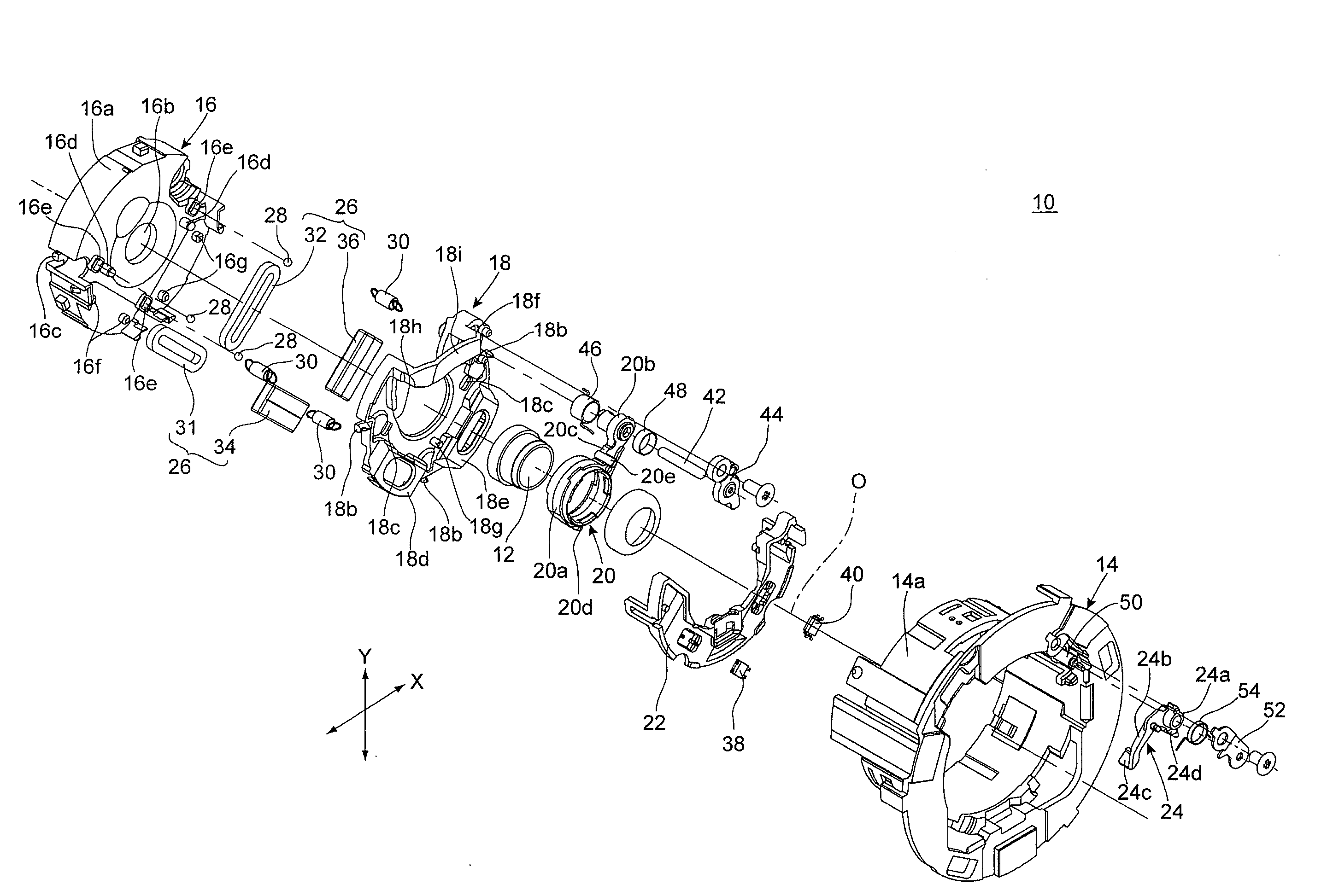
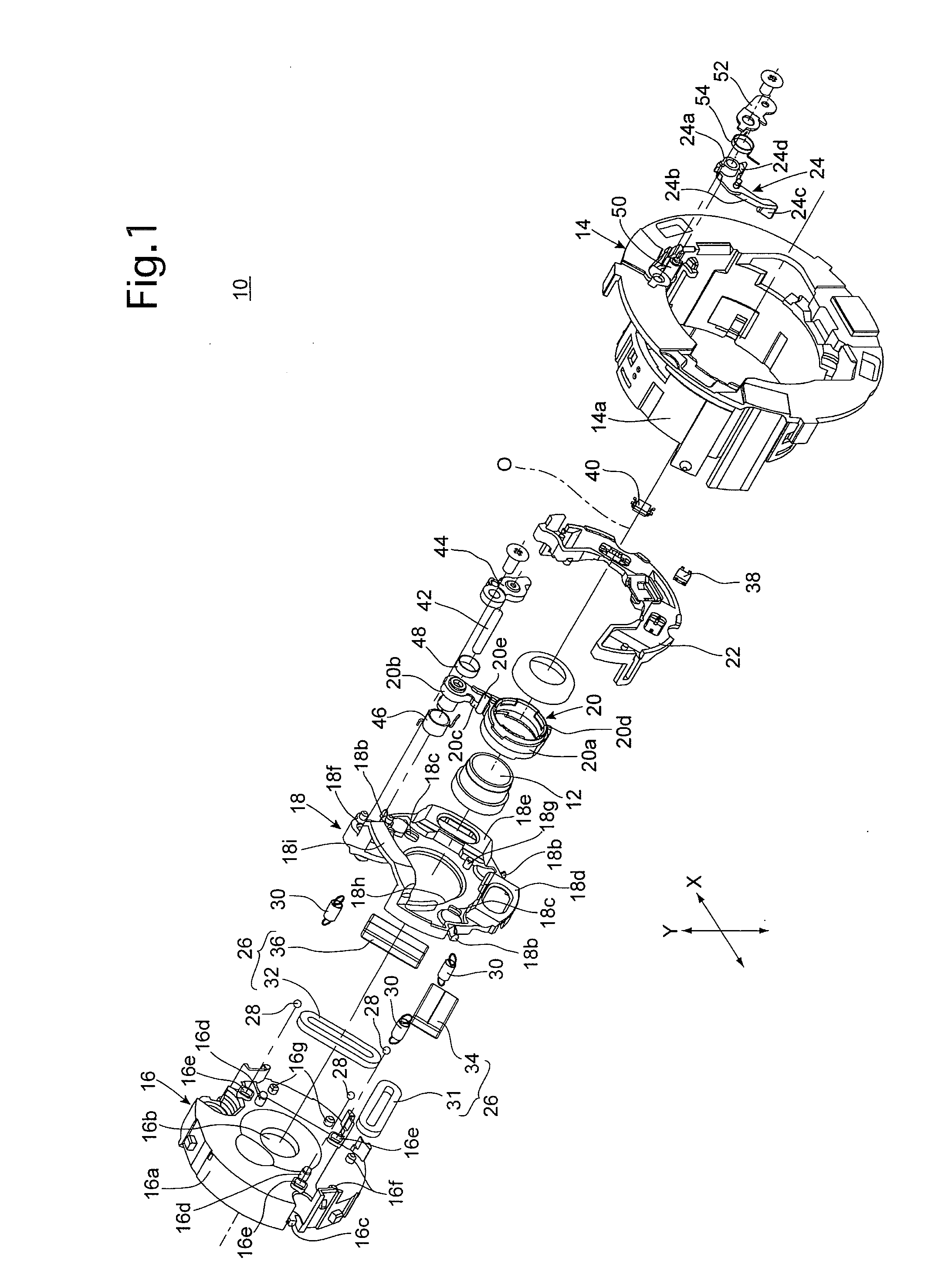
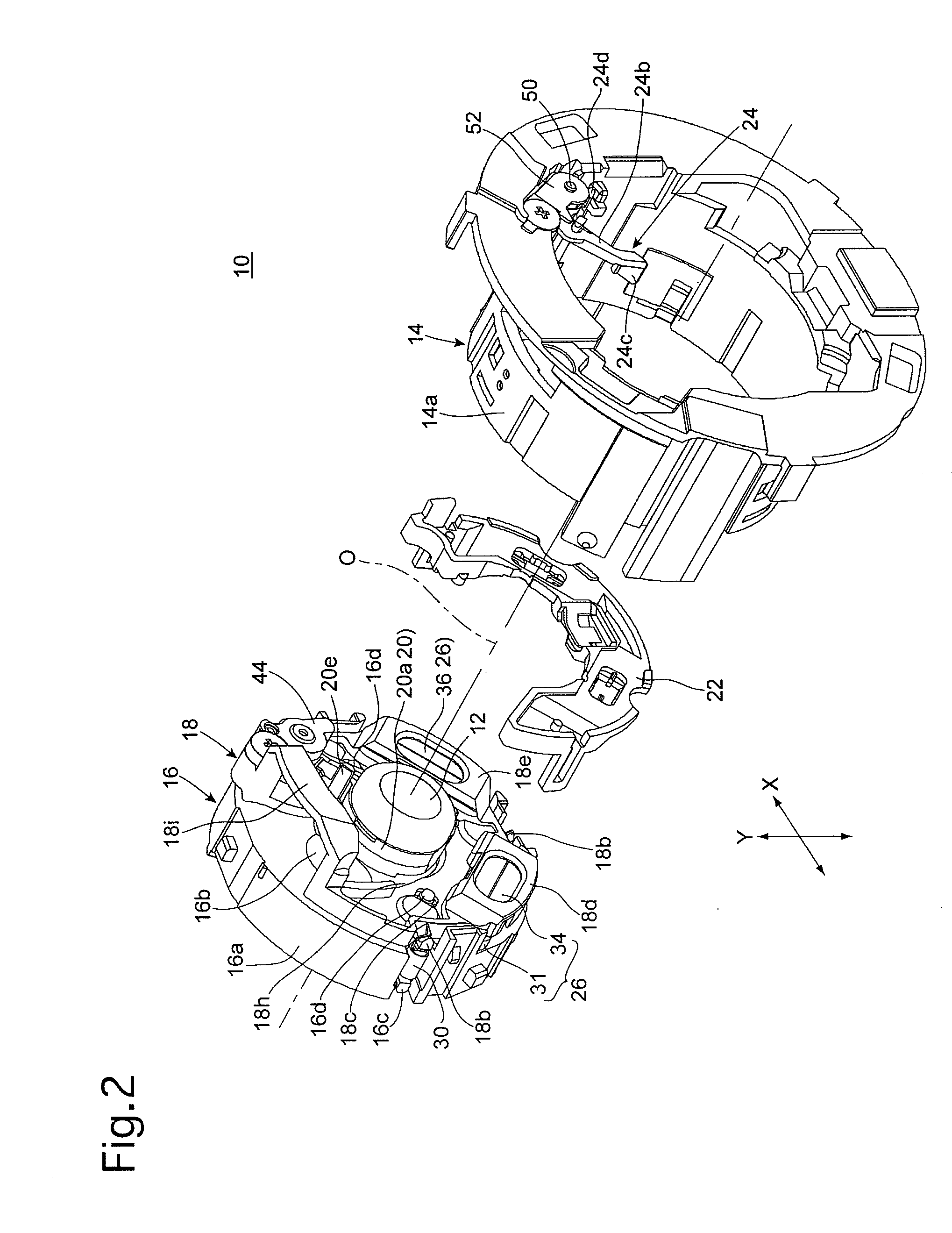
[0039]An anti-shake lens unit 10 shown in FIGS. 1 through 3 constitutes a part of a lens barrel (photographing lens) incorporated in a camera, and supports therein an insertable / removable image-stabilizing lens (removal optical element) 12 which constitutes a part of a photographing optical system of the lens barrel. As shown in FIG. 1, the anti-shake lens unit 10 is provided with a linear moving ring (advancing / retracting ring) 14, and is provided in the linear moving ring 14 with a shutter unit (advancing / retracting ring) 16, an anti-shake frame (an element of a positional adjustment mechanism / anti-shake moving member) 18, an insertable / removable frame (removable optical element holding member) 20, a sensor holder 22, a removal drive lever (removal drive member) 24, and an anti-shake drive actuator (an element of the positional adjustment mechanism / anti-shake driver) 26.

[0040]Although the overall structure of the lens barrel in which the anti-shake lens unit 10 is incorporated is ...


PUM


Abstract

A position controller for a removable optical element in an optical system includes an advancing / retracting ring; a removable optical element holding member supported by the advancing / retracting ring and rotatable about a first rotational axis between an insertion position on the optical axis and a removed position; an insertion holder which holds the removable optical element holding member at the insertion position; a removal drive member supported by the advancing / retracting ring and rotatable about a second rotational axis between an insertion allowance position and a forced removing position; and an insertion / removal controller. A rotational radius from the second rotational axis to a contact point between the removable optical element holding member and the removal drive member is greater than a rotational radius from the first rotational axis to the contact point.

Description

BACKGROUND OF THE INVENTION[0001]1. Field of the Invention[0002]The present invention relates to a position controller for a removable optical element which is moved onto and removed from a photographing optical axis in accordance with switching between a ready-to-photograph state and an accommodated state.[0003]2. Description of the Related Art[0004]A configuration in which a removable optical element, provided as part of a photographing optical system, which is movable in a plane orthogonal to an optical axis of the photographing optical system and is moved from a position on the photographing optical axis to a removed position radially away from the optical axis of the photographing optical system is known in the art as a lens-barrel (photographing lens) miniaturization technique, specifically as a technique that contributes to the reduction in thickness of a retractable lens barrel in an optical axis direction in a lens barrel accommodated state (fully retracted state) in which ...

Claims


Application Information

Patent Timeline
Patent Type & Authority Applications(United States)
IPC IPC(8): G02B27/64G02B7/14
CPCG02B7/14G02B27/646H04N5/2254G03B2217/005G03B2205/0015G03B2205/0069G03B2205/0092G03B5/00G03B2205/00H04N23/60H04N23/55G02B7/102G03B2205/0007G03B2205/0053
Inventor SUZUKA, SHINYA
Owner HOYA CORP
Why Eureka
Try Eureka