Drive mechanism and imaging device using same

Inactive Publication Date: 2012-08-30
KONICA MINOLTA OPTO
View PDF6 Cites 36 Cited by
  • Summary
  • Abstract
  • Description
  • Claims
  • Application Information

AI Technical Summary

Benefits of technology

[0009]With the foregoing in view, it is an object of the present invention to provide a drive mechanism which uses an ultrasonic linear actuator, and can suppress fluctuation in

Problems solved by technology

Therefore if an error occurs in component dimensions, the frictional force (gripping force) of the ultrasonic linear actuator fluctuates, and drive performance (e.g. velocity) becomes unstable.
However in the case of the comp

Method used


Image

  • Drive mechanism and imaging device using same
  • Drive mechanism and imaging device using same
  • Drive mechanism and imaging device using same

Examples


Embodiment Construction

[0045]An embodiment of the present invention will be described with reference to the drawings. In each drawing, composing elements denoted with a same reference symbol are identical, of which description may be omitted. In this description, a reference symbol without subscript denotes the generic name of the composing element, and a subscript is attached to a reference symbol if an individual composing element is denoted.

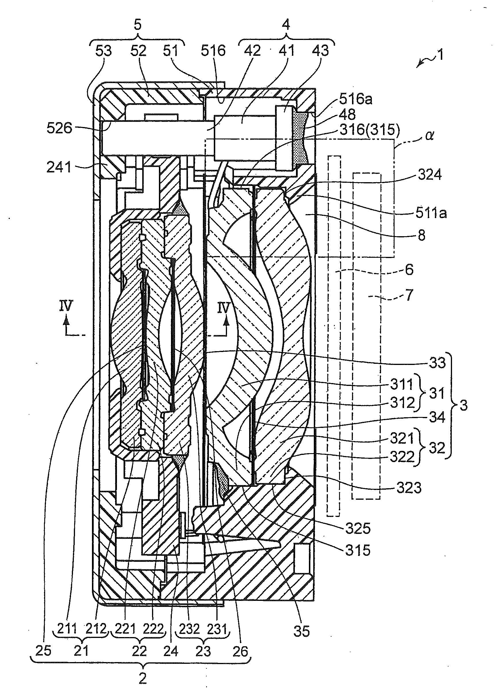
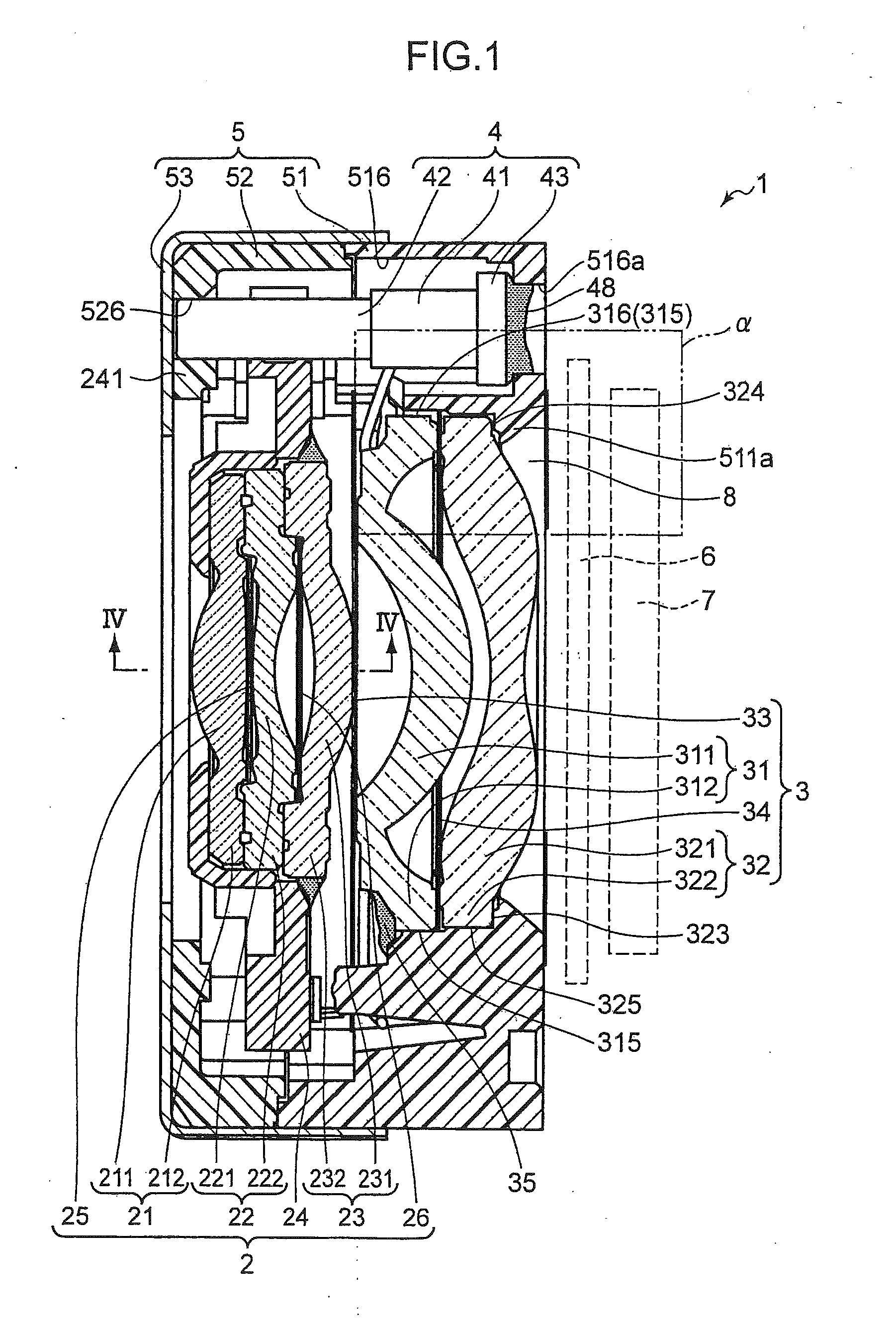
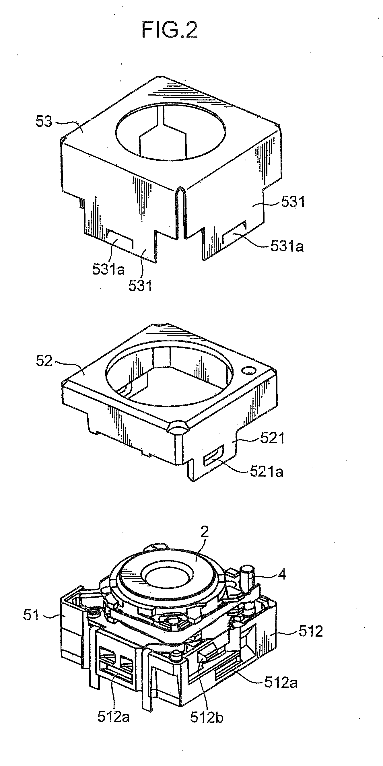
[0046]FIG. 1 is a longitudinal sectional view of an imaging device 1 according to an embodiment of the present invention. FIG. 2 is an exploded perspective view thereof, and FIG. 3 is a perspective view, which is a detailed view of FIG. 2. As FIG. 1 to FIG. 3 illustrate, this imaging device 1 comprises: a first group unit 2 which is a moving lens unit; a second group unit 3 which is a fixed lens unit; an ultrasonic linear actuator 4 which drives the first group unit 2 in the optical axis direction; an enclosure 5 which houses the first group unit 2, second group uni...


PUM


Abstract

A drive mechanism and an imaging device according to the present invention each include: an ultrasonic linear actuator 4 provided with a rod 42 that moves reciprocally in response to expansion/contraction of a piezoelectric element 41 and a first group unit 2 serving as an example of a moving body that engages with the rod 42 with a prescribed frictional force. The moving body (first group unit 2) is provided with a holding member 24, a pressing member 30 or other member that engages with the rod 42 in such a way that fluctuation in the frictional force is suppressed, and drive performance is stabilized. As a consequence, the drive mechanism and the imaging device according to the present invention can suppress fluctuation in the frictional force (gripping force) of the moving body in the ultrasonic linear actuator 4, making it possible to stabilize drive performance.

Description

TECHNICAL FIELD[0001]The present invention relates to a drive mechanism suitably used for an imaging device of a portable telephone, for example, and an imaging device using this drive mechanism, and more particularly to the drive mechanism which uses an ultrasonic linear actuator constituted by a SIDM (Smooth Impact Drive Mechanism®) for implementing auto focus and zoom functions.BACKGROUND ART[0002]In a compact lens unit used for the imaging device of a portable telephone, a drive mechanism using the ultrasonic linear actuator has been developed into practical use. This ultrasonic linear actuator transfers the expansion / contraction of a piezoelectric element to a rod, and moves the moving lens group which engages with the rod with a prescribed frictional force using the difference of velocity of the piezoelectric element upon expansion and contraction. In the case of this ultrasonic linear actuator, if the rod is expanded slowly, the moving lens group engaging with the rod with a ...

Claims


Application Information

Patent Timeline
IPC IPC(8): G02B7/04H02N2/04
CPCH02N2/025G02B7/08G02B7/04G03B13/34G03B3/10H04N23/55
Inventor ONISHI, SATOSHIKONISHI, HIROTOSHIMORITA, MITSUHIKO
Owner KONICA MINOLTA OPTO
Why Eureka
Try Eureka