Wireless LAN system
a wireless lan and access point technology, applied in the field of wireless lan systems, can solve the problems of limited location and spoilage of room interiors, and achieve the effect of improving usability
- Summary
- Abstract
- Description
- Claims
- Application Information
AI Technical Summary
Benefits of technology
Problems solved by technology
Method used
Image

Examples
application example
(3) Application Example
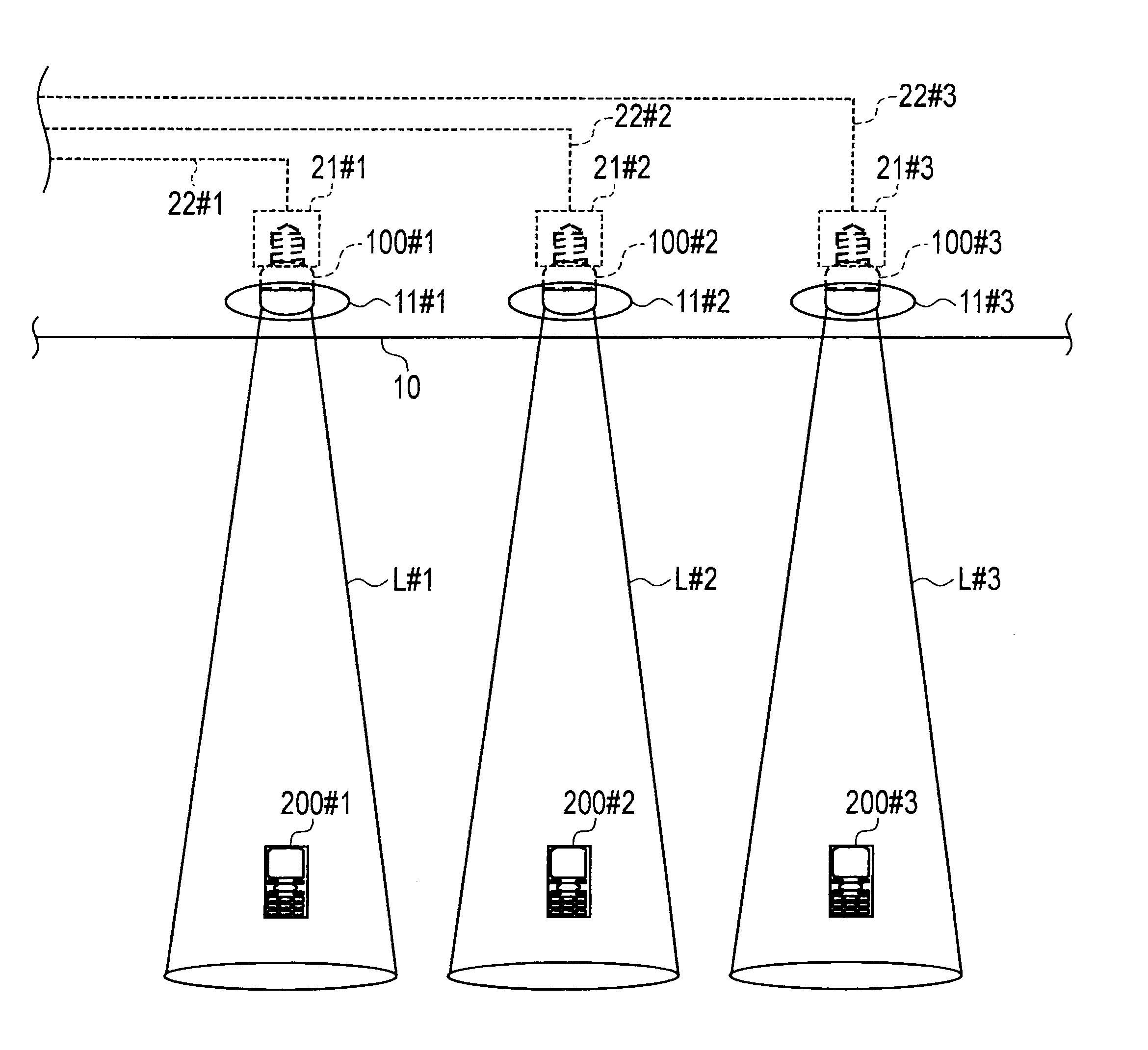
[0049]FIG. 4 shows an overall schematic configuration showing an application example of the wireless LAN system according to the embodiment described above. This application example assumes the case of providing a spot light for each of showpieces as in a museum or in a gallery, for example.
[0050]As shown in FIG. 4, in this application example, the LED light bulbs 100 (100#1 to 100#3) serving as spot lights are located close to one another. The wireless LAN terminal 200 receives a radio wave from the wireless LAN access point AP embedded in any of the LED light bulbs 100 in a position in front of one of the showpieces illuminated by the corresponding LED light bulb 100. Hence the wireless LAN terminal 200 starts wireless LAN communication with the wireless LAN access point AP. The wireless LAN access point AP stores in advance information on the corresponding showpiece and transmits the information to the wireless LAN terminal 200. Hence the wireless LAN termi...
embodiment
(4) Effect of Embodiment
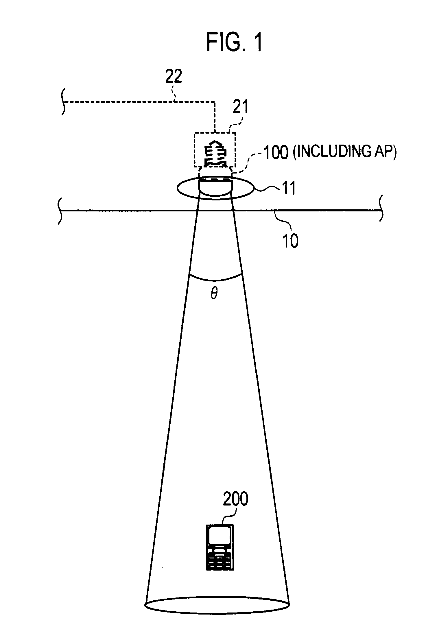
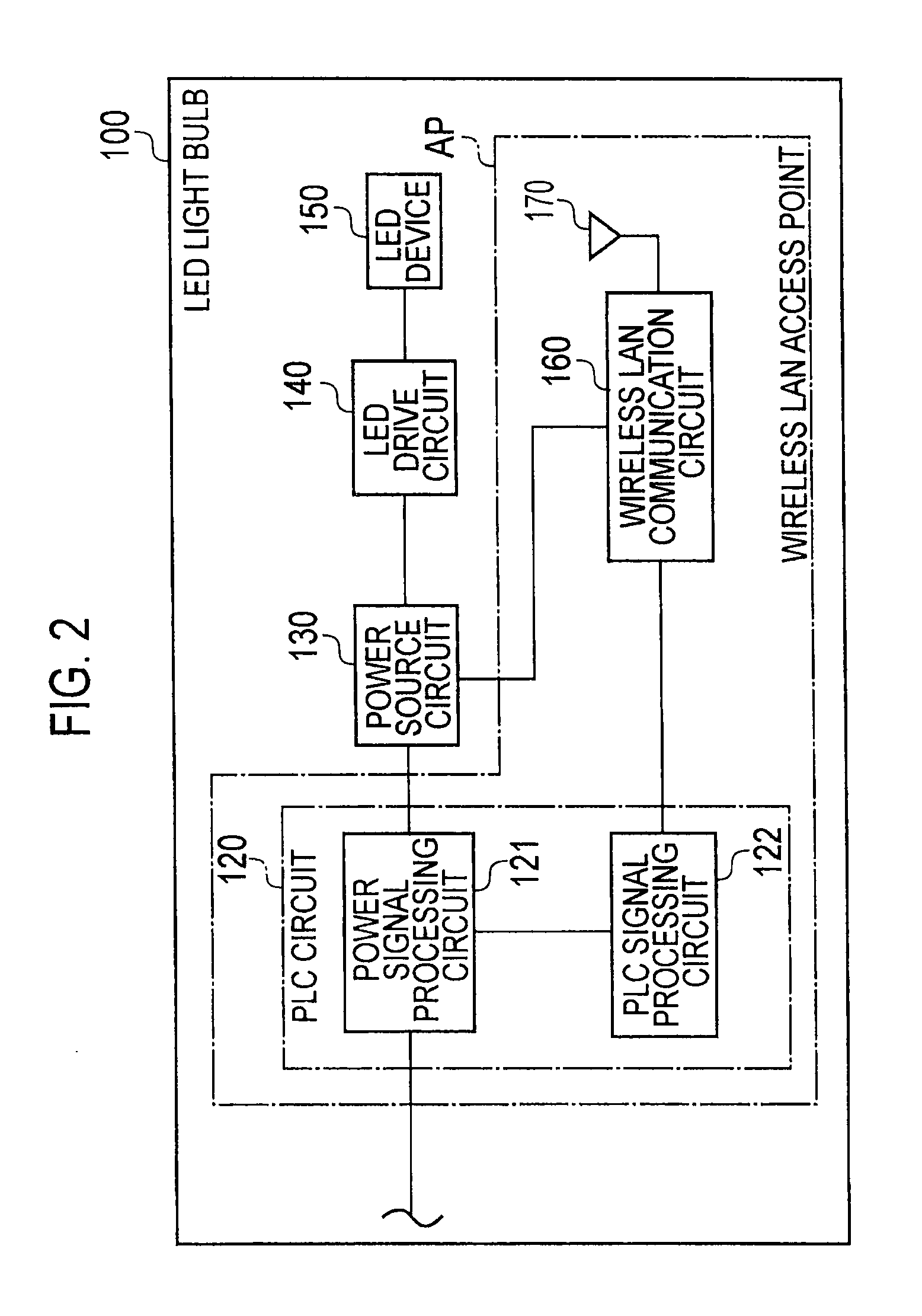
[0051]As described above, according to this embodiment, the wireless LAN access point AP is embedded in the LED light bulb 100 by utilizing the characteristics of the LED light bulb 100 of low calorific power and long product life. In this way, it is possible to establish a wireless LAN environment just by plugging the LED light bulb 100 into the socket 21 and to enhance usability.
[0052]Moreover, according to this embodiment, the wireless LAN access point AP emits the radio waves in the radio wave emission pattern matching entirely or almost entirely with the light irradiation pattern at the limited light irradiation angle. This can lower the possibility of an interference with radio waves from another wireless LAN access point. Here, the LED light bulb 100 and the wireless LAN access point AP are integrated. Hence the light irradiation pattern can be matched entirely or almost entirely with the radio wave emission pattern in advance. Moreover, a user who own...
PUM
 Abstract
Description
Claims
Application Information
 - R&D
- Intellectual Property
- Life Sciences
- Materials
- Tech Scout
- Unparalleled Data Quality
- Higher Quality Content
- 60% Fewer Hallucinations
Browse by: Latest US Patents, China's latest patents, Technical Efficacy Thesaurus, Application Domain, Technology Topic, Popular Technical Reports.
© 2025 PatSnap. All rights reserved.Legal|Privacy policy|Modern Slavery Act Transparency Statement|Sitemap|About US| Contact US: help@patsnap.com