Controllable filter to diagonalize a transmission channel

a controllable filter and transmission channel technology, applied in the field of wireless communication network nodes, can solve the problems of unwanted noise amplification limiting the performance, the complexity of the methods used for combating interference, and the parts of air interface resources

Active Publication Date: 2012-08-30
TELEFON AB LM ERICSSON (PUBL)
View PDF4 Cites 2 Cited by
  • Summary
  • Abstract
  • Description
  • Claims
  • Application Information

AI Technical Summary

Benefits of technology

[0009]It is thus an object of the present invention to provide an enhanced estimation of a channel starting from received pilot sequences, which is not as vulnerable to passing time as for presently employed channel estimation.

Problems solved by technology

However, such a scheme would in most cases lead to unwanted noise amplification limiting the performance.
The complexity of the methods used for combating the interference competes with a desire to cancel the interference to as large extent as possible.
A consequence is that parts of the air interface resources (spectrum, time, codes) are occupied with pilots, and can then not be used for transmitting data.
Each pilot sequence is only transmitted during certain time and frequency periods, and a consequence of this is that as time progresses, the estimate becomes less good due to a variation of the channel.
Differently stated, it means that the error of the channel estimate increase as a function of time.
One implication of an error increase is that the user data through-put decrease.
Also, pre-coders suffer in terms of less reliable weights.
That is, there is a larger uncertainty regarding where to place the antenna beam energy.
This results in computationally complex algorithms in which various parameters such as Doppler shift, Doppler spread and delay spread are needed components.

Method used


Image

  • Controllable filter to diagonalize a transmission channel
  • Controllable filter to diagonalize a transmission channel
  • Controllable filter to diagonalize a transmission channel

Examples


Embodiment Construction

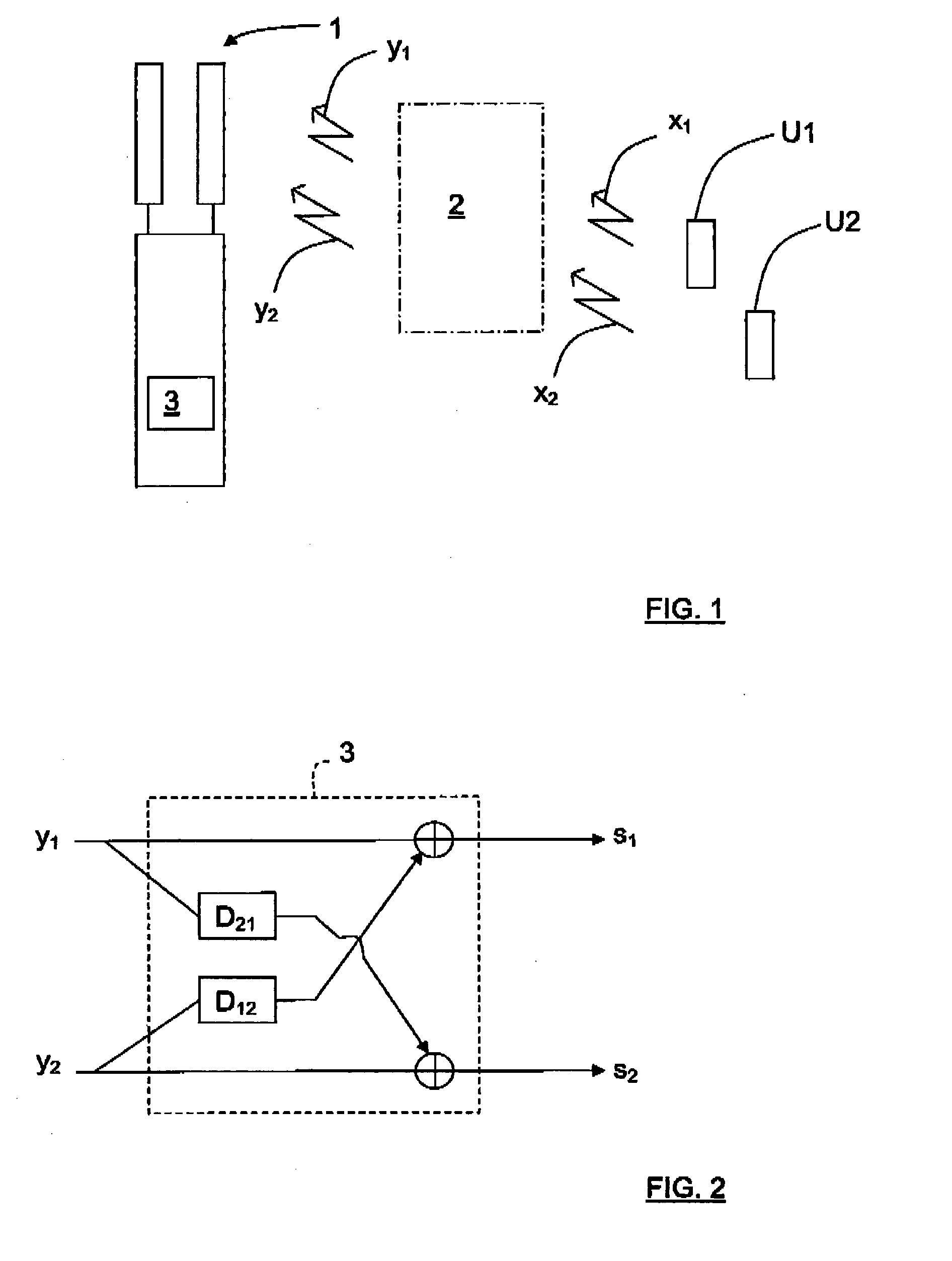
[0021]The present description will be based on the following data model of the observation:

y(n)=H(q1)x(n)+w(n),   (1)

where x(n) is a vector of N independent transmitted signal streams at a time n, y(n) is the corresponding observations subject to a frequency selective channel matrix H(q−1), and the term w(n) is a noise vector comprising interference and noise.

[0022]In equation (1), q−1 is the so-called unit delay operator, which is defined as:

q−1x(n)=x(n−1).

[0023]When using equation (1) as a data model, it is possible to estimate the channel parameters in for example a least squares sense according to equation (2) below during a pilot block.

θ^=argminθEy(n)-H(q-1;θ)·x(n)2,(2)

where θ is a parameterization of the channel model. Equation (2) states that the estimated parameters are obtained by minimizing the mean square error.

[0024]The obtained estimate {circumflex over (θ)} is expected to be close to a true parameter vector θ0.

[0025]To elaborate on the model described by equation (1), ...


PUM


Abstract

The present invention relates to a node (1) in a wireless communication network, where the node (1) is arranged to receive at least two signals (y1(n), y2(n)) which correspond to at least two transmitted uncorrelated signal streams (x1(n), X2(n)) which have been transmitted to the node via a channel. The channel (2) is signals represented by means of a channel matrix (H(q−1)). The node (1) comprises a controllable filter structure (3) that is arranged to diagonalize the channel matrix (H(q−1)) such that a channel matrix estimation (Ĥ(q−1)) may be obtained. The present invention also relates to a corresponding method.

Description

TECHNICAL FIELD[0001]The present invention relates to a node in a wireless communication network, where the node is arranged to receive at least two signals which correspond to at least two transmitted uncorrelated signal streams which have been transmitted to the node via a channel, which channel is represented by means of a channel matrix.[0002]The present invention also relates to a method for a node in a wireless communication network, where the method comprises the step of receiving at least two signals at the node, which signals correspond to at least two transmitted uncorrelated signal streams which have been transmitted to the node via a channel, which channel is represented by means of a channel matrix.BACKGROUND[0003]In wireless communication systems, a transmitted signal is distorted due to dynamic properties of a radio channel through which it is transmitted. In order to compensate for the dynamic properties of the radio channel, different methods are available for comba...

Claims


Application Information

Patent Timeline
Patent Type & Authority Applications(United States)
IPC IPC(8): H04B1/10H04L27/06
CPCH04L25/0242H04L25/03993H04L25/03114
Inventor LINDGREN, ULFSAHLIN, HENRIK
Owner TELEFON AB LM ERICSSON (PUBL)
Why Eureka
Try Eureka