Pulse detector

a pulse wave and detector technology, applied in the field of pulse detectors, can solve the problems of large noise intermixed with the pulse wave signal output, few arterial blood vessels, and difficult to see the motion of the heartbeat in the venous bloodstream, so as to reduce the occurrence of pulse detection failures and detection errors, reduce the effect of filter configuration and effective us

Active Publication Date: 2012-08-30
SEIKO EPSON CORP
View PDF8 Cites 11 Cited by
  • Summary
  • Abstract
  • Description
  • Claims
  • Application Information

AI Technical Summary

Benefits of technology

[0046]In accordance with the present aspect, the adaptive filters can be switched with suitable timing. Therefore, the performance of the adaptive filters can be kept at a suitable level even in the case of long periods of continuous measurement. It is thereby possible to reduce the occurrence pulse detection failures and detection errors.
[0047]In this manner, in accordance with at least one aspect of the invention described above, the adaptive filters constituting the pulse wave signal filtering section are switched, e.g., with suitable timing, whereby it is possible to keep the performance of the adaptive filters at a suitable level. Since the adaptive filters are effectively used, the filter configuration can be simplified and the adaptive filters can be switched with relative ease. It is therefore possible to realize a pulse detector that can carry out effective noise countermeasures while the processing load of the device is reduced.

Problems solved by technology

Therefore, there is a large amount of noise intermixed with the pulse wave signal outputted from the pulse wave sensor when the pulse wave sensor is worn in such locations.
A wrist-type pulse detector (a pulse detector of a type that is worn on the wrist of a human or the like) in particular requires sufficient noise countermeasures because the resulting pulse wave signal is weaker than a finger-type pulse detector (a pulse detector of a type that is worn on the finger of a human or the like).
The motion of the heartbeat is difficult to see in the venous bloodstream.
However, there are few arterial blood vessels in the subcutaneous tissue (shallow areas) on the external side of the wrist.
For this reason, there is a high possibility that changes in the bloodstream will become difficult to see due to wrist motion or when an impact occurs around the hand.

Method used


Image

  • Pulse detector
  • Pulse detector
  • Pulse detector

Examples


first embodiment

Overall Configuration Example

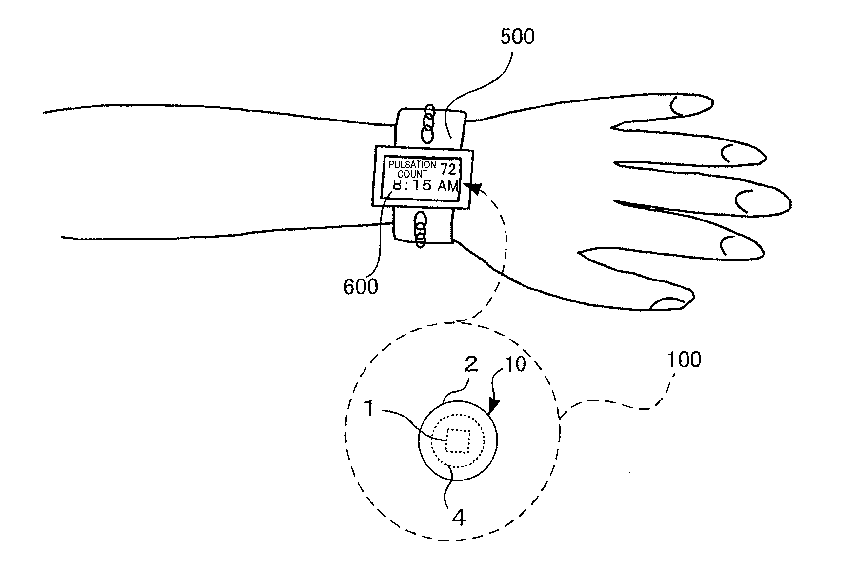
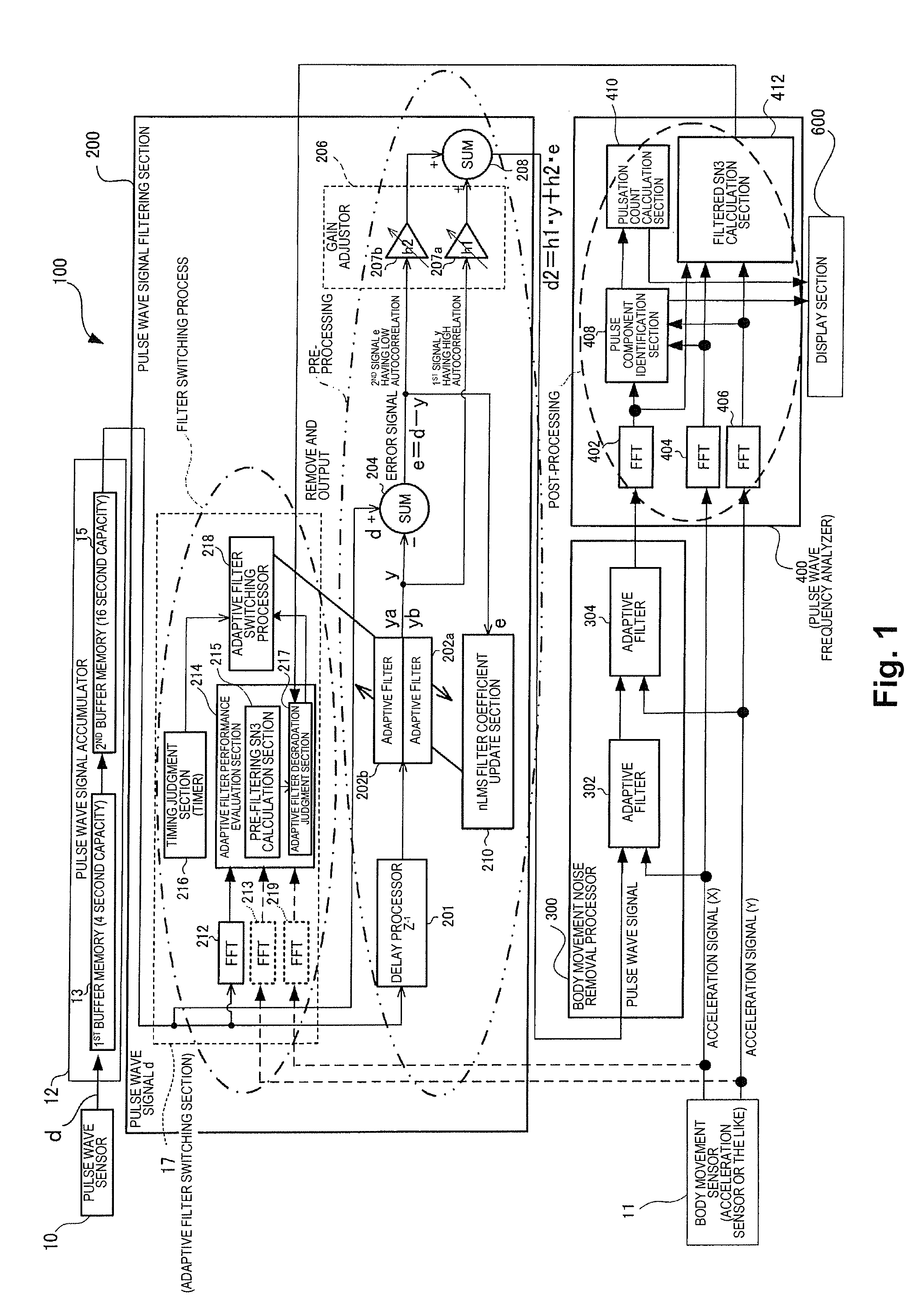
[0059]FIG. 1 is a view showing the configuration of an example of the pulse detector of the invention. The pulse detector 100 shown in FIG. 1 is a type of sensor device for detecting a pulse signal originating in the pulse of a subject (including humans and animals), as well as a heartbeat, and other biological information or the like that correspond to a pulse signal.

[0060]Here, the word “pulse” in a medical context refers to activity that occurs when periodic contractions and relaxations of the heart as well as internal organs in general are repeated. As used herein, the term “pulse” refers to pumping motion in which the heart periodically sends blood. A heartbeat count is referred to as the number of pulses of the heart in a single minute. The pulsation count is the number of pulsatory motions in a peripheral blood vessel. This number of times thus counted shall be referred to as a “pulsation count” or merely as a “pulsation” because pulsatory motions...

second embodiment

[0166]FIGS. 9A and 9B are views showing the result of examining fluctuation of the S / N index (SN3) in each example of switching adaptive filters and in an example without switching (comparative example) in response to elapsed time.

[0167]Here, a subject wears the wristwatch-type pulse rate meter (i.e., pulse detector 100), and walks for 20 minutes. The pulse wave signal is filtered by the adaptive filters, the S / N index (SN3) is calculated for the filtered signal, and the calculation results are plotted on the time axis.

[0168]In FIGS. 9A and 9B, the horizontal axis is the time axis, and the vertical axis is an axis showing the values (%) of SN3, which is the S / N index. FIG. 9A shows the change in SN3 over time until 10 minutes have elapsed from the start of walking by the user as the subject. FIG. 9B shows the change in SN3 over time until 20 minutes have elapsed from a time point at which 15 minutes have elapsed. Also, the data that corresponds to the present embodiment is shown by ...


PUM


Abstract

A pulse detector (100) includes a pulse wave sensor (10); a pulse wave signal filtering section (200) having a first adaptive filter (202a) and second adaptive filter (202b), and an adaptive filter switching section (17); and a pulse wave frequency analyzer (400), wherein the adaptive filter switching section (17) starts an adaptive processing of the second adaptive filter (202b) at a first time point partway through a second interval in which the first adaptive filter (202a) is continuously carrying out adaptive processing, where the second interval occurs in the first interval, and switches from the first adaptive filter (202a) to the second adaptive filter (202b) at a second time point, which is a time point after the first time point and which is the end point of the second interval.

Description

CROSS-REFERENCE TO RELATED APPLICATIONS[0001]This application claims priority to Japanese Patent Application No. 2011-041490 filed on Feb. 28, 2011. The entire disclosure of Japanese Patent Application No. 2011-041490 is hereby incorporated herein by reference.BACKGROUND[0002]1. Technological Field[0003]The present invention relates to a pulse detector and the like.[0004]2. Background Technology[0005]A pulse detector is a device for detecting a pulse originating from a human heartbeat, and is a device for removing as noise a signal component (body movement effect signal) generated by the effects of human body movements from a signal (pulse wave signal) received from a pulse wave sensor worn on, e.g., the arm, palm, finger, or the like to detect a signal (pulse signal) derived from a heartbeat.[0006]A pulse wave sensor of a type that is worn on a human finger or wrist is disclosed in, e.g., Patent Document 1. Art for filtering out and removing a noise component included in the pulse ...

Claims


Application Information

Patent Timeline
Patent Type & Authority Applications(United States)
IPC IPC(8): A61B5/0205
CPCA61B5/024A61B5/02416A61B5/7207A61B5/681A61B5/721A61B5/02438
Inventor TAKAHASHI, YUSUKE
Owner SEIKO EPSON CORP
Why Eureka
Try Eureka