
Intermedullary system and method

a technology of intramedullary rods and rods, applied in the field of intramedullary rod systems and methods, can solve the problems of much faster process of accurately drilling through the bone and locating the holes in the intramedullary rods than conventional methods

Inactive Publication Date: 2012-08-30
DISTALOCK LLC
View PDF4 Cites 22 Cited by
  • Summary
  • Abstract
  • Description
  • Claims
  • Application Information

AI Technical Summary

Benefits of technology

[0010]An orthopedic device and method for facilitating the fixation of a distal portion of a device to a bone is provided. In one exemplary embodiment, the orthopedic device and method can facilitate accurate distal fixation of an intramedullary rod within a fractured or damaged bone where the distal fixation area is difficult to locate. Because the devices and methods of the invention do not typically require the use of x-rays or other scanning techniques, the amount of radiation to which the physician is exposed during the distal fixation process is greatly reduced or eliminated. In addition, the process of accurately drilling through the bone and locating corresponding holes in intramedullary rod is much faster than conventional methods that rely primarily on radiation screening and trial-and-error techniques for proper screw placement.
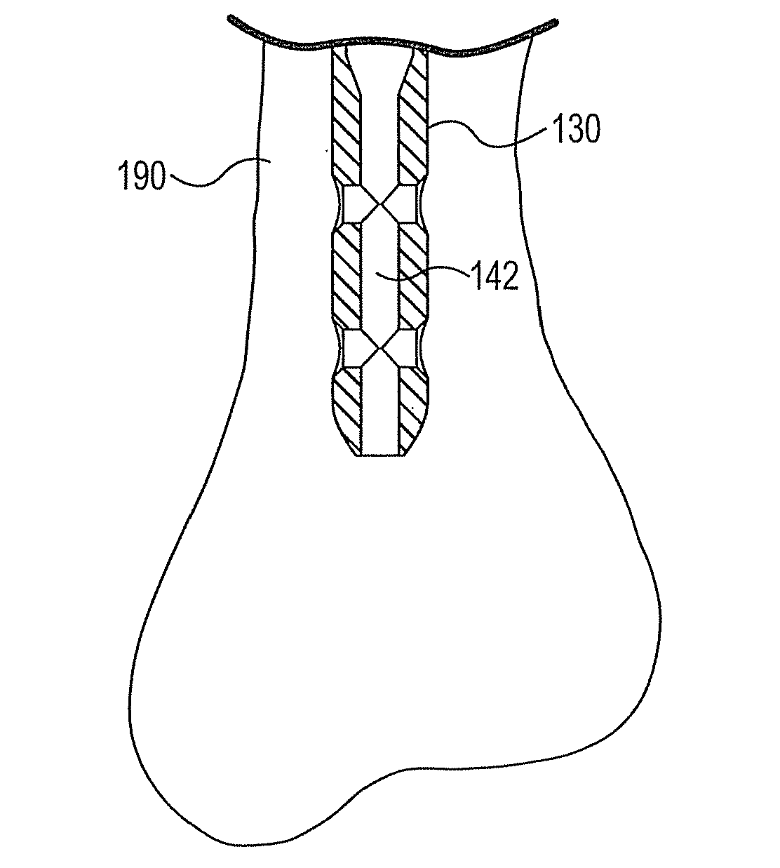
[0011]The orthopedic method of the invention may include the use of a bone drill structured for accurately locating the distal holes of an implanted intramedullary rod from within the rod. In particular, such bone drills may drill outwardly from inside intramedullary rod through the thickness of the bone and adjacent tissue. By drilling from inside the rod and using the distal holes to locate the drilling site, the drilled holes are accurately aligned with the distal holes in the rod. This enables the operator to easily and accurately place the screws in their desired locations to fix the distal portion of intramedullary rod to the broken bone.
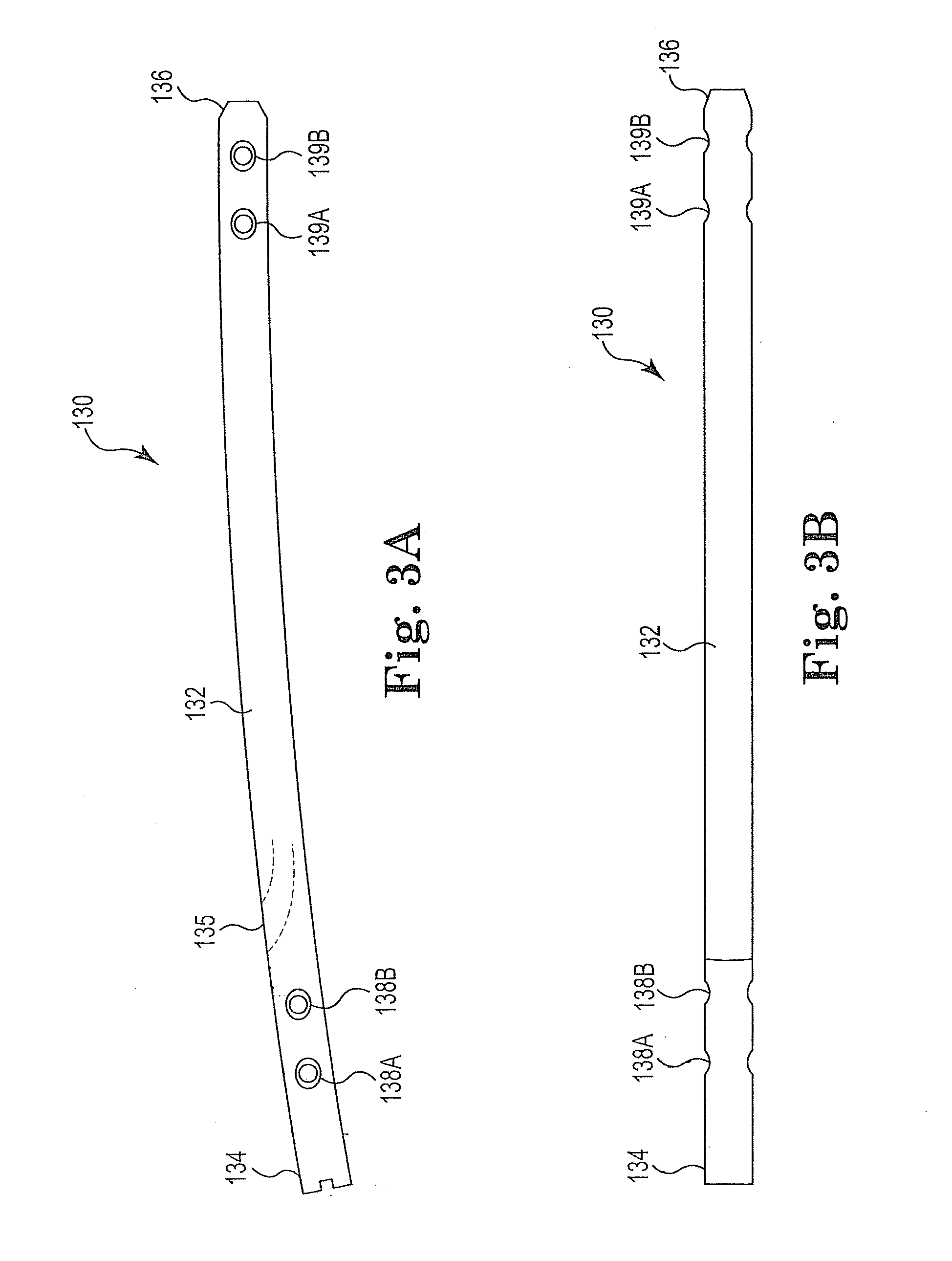
[0012]In one aspect of the present invention, an intramedullary rod structured for positioning within an inner cavity of a bone comprises an elongate body having a proximal end, a distal end, and a channel formed therein, at least one distal hole near the distal end of the elongate body, and locating means formed within the channel of the elongate body. The locating means is structured to allow a surgeon to locate the at least one distal hole with a drilling means from within the channel. The locating means is also structured to support the drilling means when the drilling means is being operated to drill a pilot hole through a bone. Drilling a pilot hole from within an inner cavity of a bone allows the surgeon to determine the angular position of intramedullary rod with respect to the bone.
[0015]In another aspect, the step pin comprises a first elongate portion having an interface means for interfacing with a driving means, wherein the driving means operably rotates the step pin, and a second elongate portion having a generally conical distal tip and a threaded outer surface. The first elongate portion is structured to be received within an inner channel of a cannulated drill bit so as to guide the cannulated drill bit. The second elongate portion is structured to be rotatably driven into a pilot hole extending through a portion of a bone, wherein the threaded outer surface of the second elongate portion provides a secure engagement between the step pin and the bone.

Problems solved by technology

In addition, the process of accurately drilling through the bone and locating corresponding holes in intramedullary rod is much faster than conventional methods that rely primarily on radiation screening and trial-and-error techniques for proper screw placement.

Method used


Image

  • Intermedullary system and method
  • Intermedullary system and method
  • Intermedullary system and method

Examples


Embodiment Construction

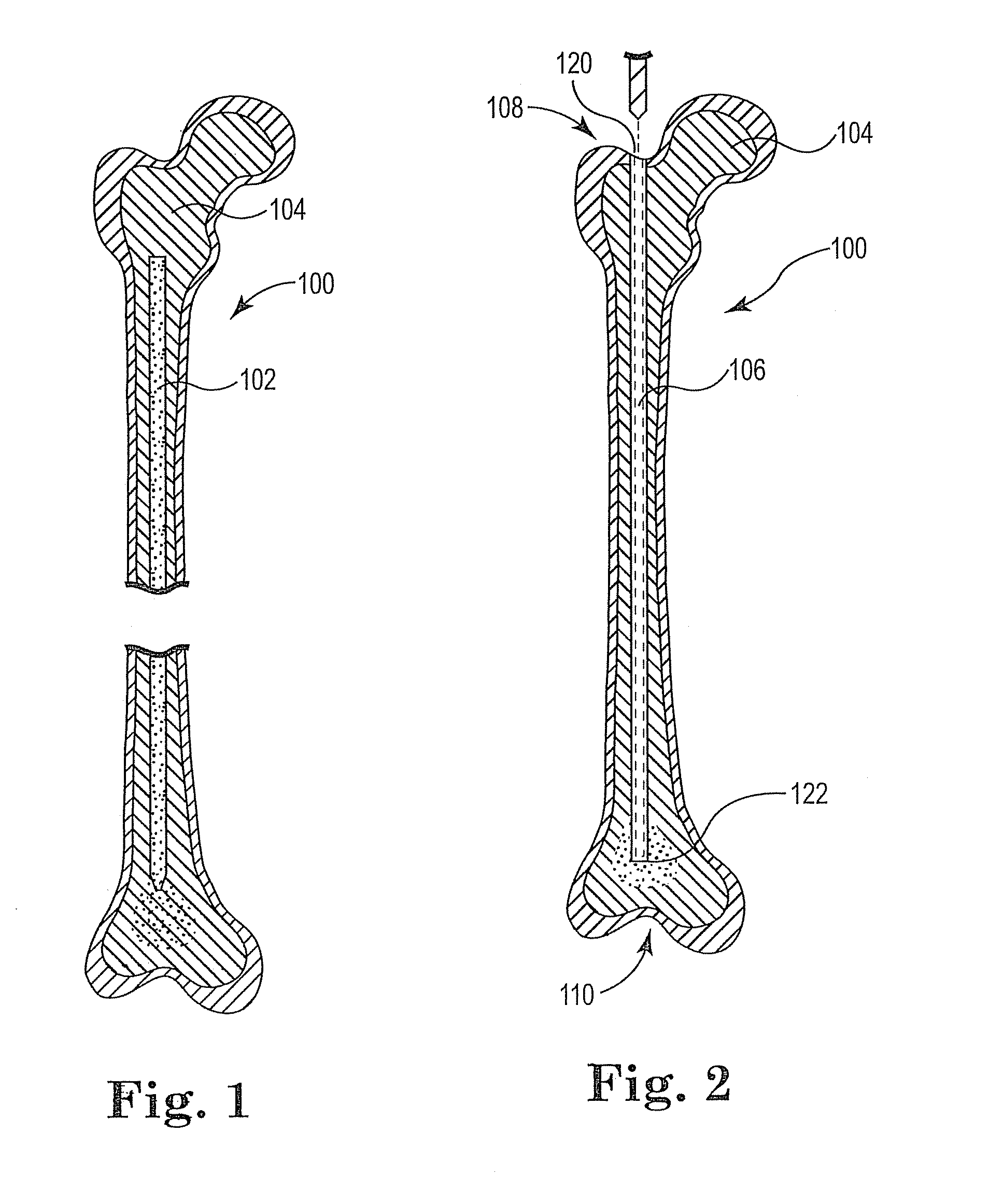
[0037]FIG. 1 is a cross-sectional view illustrating two portions of a broken femur 100. While the break is generally illustrated as a clean fracture of the bone into two portions, it is possible that the femur could instead be fractured into a number of smaller bone fragments or damaged in some other way. Thus, it should be understood that the devices and methods described herein for two bone pieces can also apply to three or more bone pieces or fragments or even a cracked bone that has not separated into multiple pieces. The femur 100 includes cancellous tissue 104 and an intramedullary cavity 102 that extends along a portion of the length of the femur 100 within the tissue 104. The intramedullary cavity 102 is a generally open area in the femur that is filled or partially filled with bone marrow. In order to prepare a bone such as the femur 100 for insertion of an intramedullary rod therein, the intramedullary cavity 102 can be aspirated and / or lavaged to remove some or all of the...


PUM


Abstract

A system and method for drilling soft tissue and positioning an intramedullary rod in a long bone is provided. The system includes an intramedullary rod having an internal channel sized to provide a tight fit for a drill assembly. The system also includes a step pin used for marking the position of a pilot hole drilled through the bone within which the intramedullary rod is positioned.

Description

BACKGROUND OF INVENTION[0001]1. Field of Invention[0002]The present invention relates to a system and method for drilling soft tissue and positioning an intramedullary rod in a long bone.[0003]2. Description of the Related Art[0004]Intramedullary rods are commonly used in orthopedic surgery for breaks in the long bones of the extremities, such as the femur and tibia. These rods are used to align and stabilize fractures or breaks of bones and to maintain the bone fragments in their proper alignment relative to each other during the healing process. In addition, intramedullary rods can provide strength to the bone during the convalescence of the patient. One common surgical rod implantation procedure involves drilling the bone marrow canal of the fractured bone from a proximal to a distal end of the bone and inserting an intramedullary rod into this evacuated space. In order to maintain the intramedullary rod in the proper relationship relative to the bone fragments, it is often desir...

Claims


Application Information

Patent Timeline
Patent Type & Authority Applications(United States)
IPC IPC(8): A61B17/72A61B17/17
CPCA61B17/1615A61B17/1631A61B17/8897A61B17/1725A61B17/72A61B17/1633
Inventor CORNEILLE, PATRICK R.PFAHNL, ANDREAS CARLMCMAHAN, MARK A.GRAHAM, GARY L.LING, JEREMY J.
Owner DISTALOCK LLC
Learn More