
Architecture, system, method, and computer-accessible medium for partial-scan testing

a partial scan and architecture technology, applied in the direction of testing circuits, resistance/reactance/impedence, instruments, etc., can solve the problems of performance and test costs, controllability and observability of flip-flops can be compromised, and the computational cost of sequential atpg typically cannot be afforded, so as to achieve the effect of reducing the cost of full scan, avoiding the effect of affecting the performance of the full scan

Active Publication Date: 2012-08-30
NEW YORK UNIV IN ABU DHABI CORP
View PDF8 Cites 9 Cited by
  • Summary
  • Abstract
  • Description
  • Claims
  • Application Information

AI Technical Summary

Benefits of technology

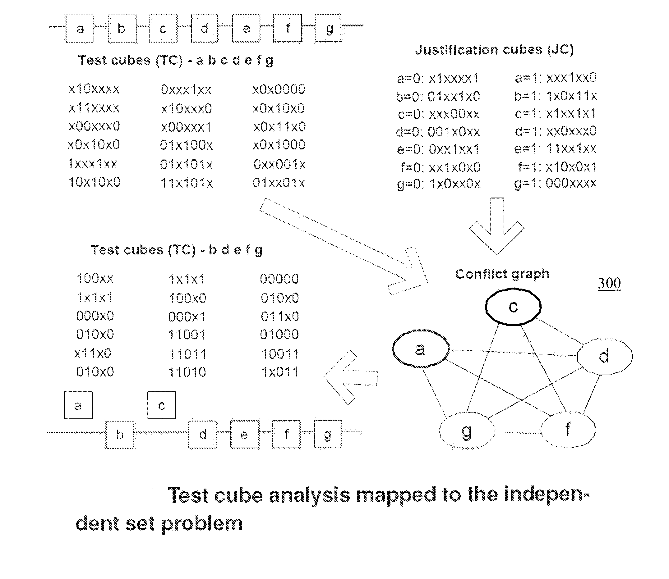
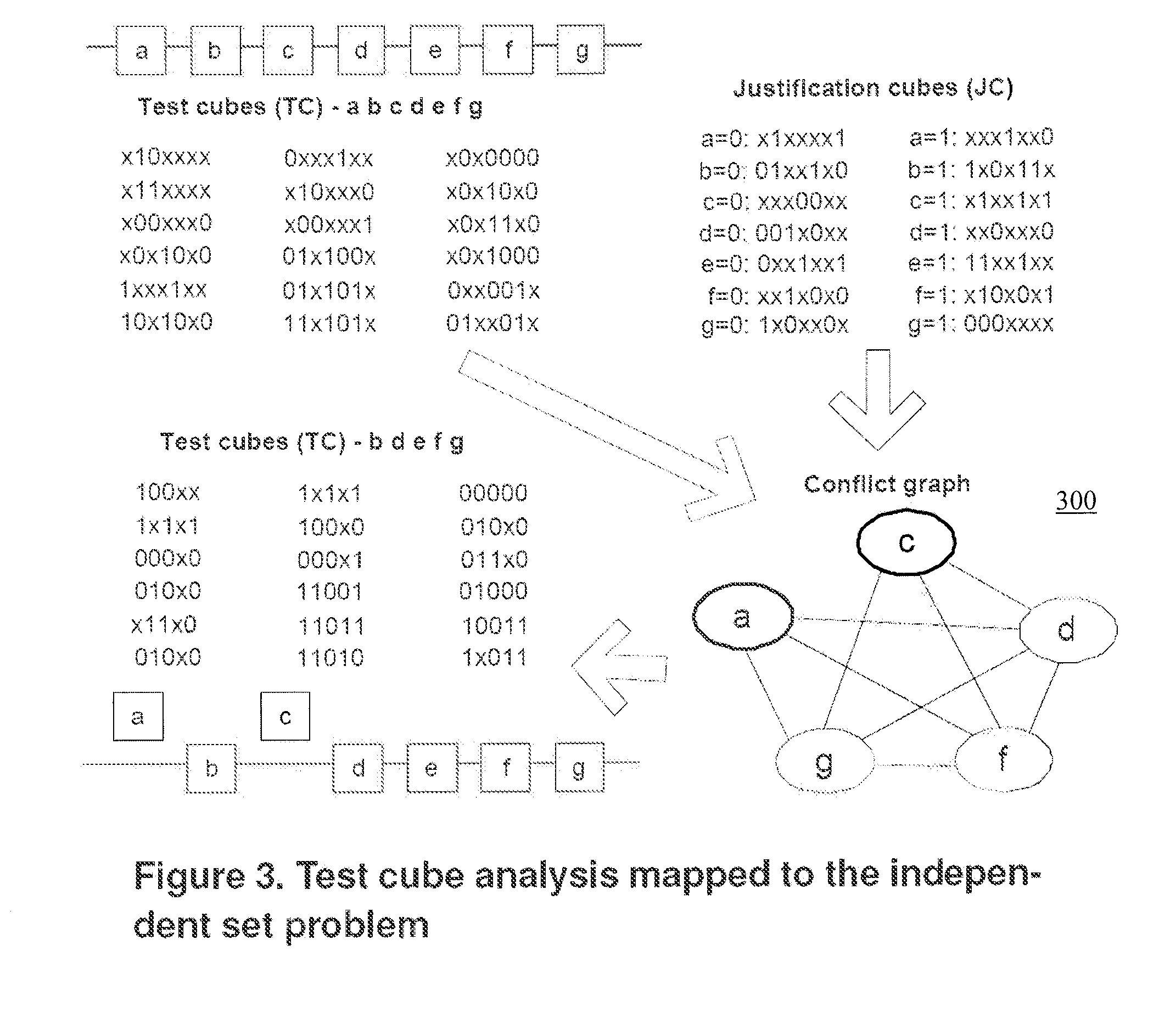
[0011]Exemplary embodiments of the present disclosure can provide a test cube analysis driven partial scan scheme. The exemplary technique can operate on a set of test cubes generated by a combinational Automatic Test Pattern Generation (ATPG) tool, and can identify a maximum number of flip-flops that can be converted to non-scan while delivering the quality of full scan.
[0012]By identifying the conditions to recover the controllability and observability compromised due to partial scan, and by formulating these conditions via test cube operations, an exemplary computationally efficient partial scan scheme that is compatible with the conventional ATPG flow can be provided. Upon the identification of the flip-flops that can be converted to non-scan, the test cubes can be post-processed to ensure the delivery of the original set intact into the flip-flops. This simple exemplary post-processing procedure, which can be based on cube merge operations, can reduce or even eliminate the need for an ATPG re-run.
[0013]The exemplary partial scan scheme can preferably combine the simplicity of the conventional (full scan-based) ATPG flow, and the area, performance, test time, and test power reduction benefits of partial scan. The removal of scan multiplexers can deliver area as well as performance savings, while the shortening of the scan path can translate into test time and data volume reductions. Furthermore, as the non-scan flip-flops are typically inactive during shift operations, power dissipation in the scan path, in the combinational logic, and in the clock tree can be reduced. The proposed partial scan scheme can be applied in conjunction with test compression and test power reduction techniques to drive the test costs down even further.

Problems solved by technology

Increasing complexity of integrated circuits has generally forced the industry to abandon partial scan, which can remove scan multiplexers corresponding to some of the flip-flops, disconnecting them from the scan path.
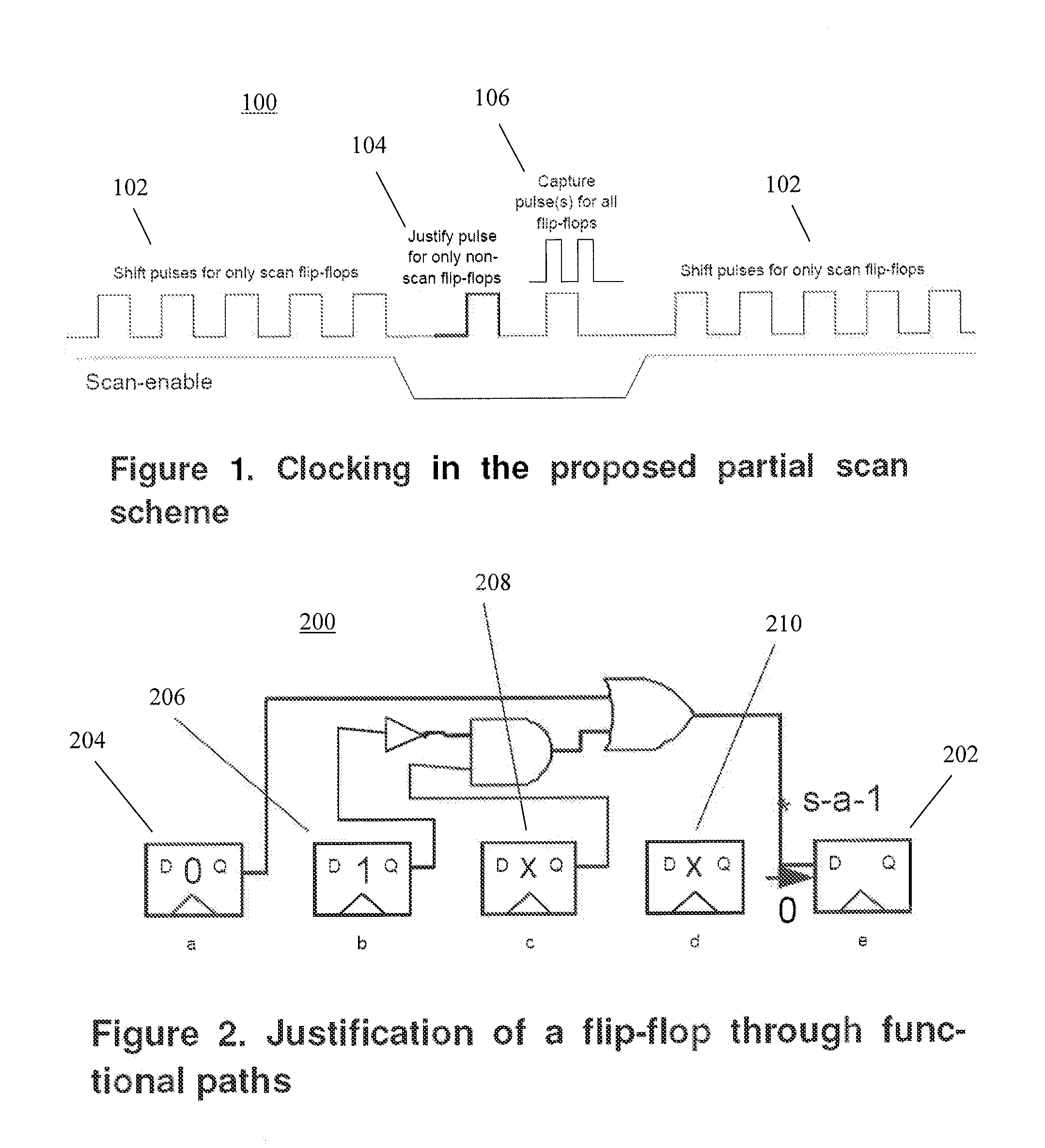
As a result, controllability and observability of these flip-flops can be compromised, typically necessitating sequential Automatic Test Pattern Generation (ATPG), where these flip-flops can be controlled and observed through functional paths.
The computational cost of sequential ATPG typically cannot be afforded, given the complexity of integrated circuits today.
Full scan typically incurs area, performance and test costs.
An insertion of as many multiplexers as the number of flip-flops in the design can impose a considerable area cost.
Furthermore, these multiplexers are typically inserted on functional paths, resulting in critical path prolongation by a multiplexer delay, and hence degrading the performance of the design timing-wise.
Full scan can also incur significant test costs.
Another problem that full scan imposes can be the excessive switching activity during test, as all the flip-flops are active during shift operations.
80-90, May 2002) occur during testing, which, if overlooked, can cause reliability issues.
These techniques typically necessitate the utilization of sequential ATPG or combinational ATPG with time frame expansion to generate test patterns on the partially scanned design, not only failing to comply with the existing design / test flow that industry utilizes today but also typically incapable of ensuring the quality of full scan.

Method used


Image

  • Architecture, system, method, and computer-accessible medium for partial-scan testing
  • Architecture, system, method, and computer-accessible medium for partial-scan testing
  • Architecture, system, method, and computer-accessible medium for partial-scan testing

Examples


Embodiment Construction

[0011]Exemplary embodiments of the present disclosure can provide a test cube analysis driven partial scan scheme. The exemplary technique can operate on a set of test cubes generated by a combinational Automatic Test Pattern Generation (ATPG) tool, and can identify a maximum number of flip-flops that can be converted to non-scan while delivering the quality of full scan.

[0012]By identifying the conditions to recover the controllability and observability compromised due to partial scan, and by formulating these conditions via test cube operations, an exemplary computationally efficient partial scan scheme that is compatible with the conventional ATPG flow can be provided. Upon the identification of the flip-flops that can be converted to non-scan, the test cubes can be post-processed to ensure the delivery of the original set intact into the flip-flops. This simple exemplary post-processing procedure, which can be based on cube merge operations, can reduce or even eliminate the need...


PUM


Abstract

Exemplary method, computer-accessible medium, test architecture, and system can be provided for a partial-scan test of at least one integrated circuit. For example, it is possible to obtain a plurality of test cubes using a first combinational automatic test pattern generation (ATPG) and identify at least one flip-flop of the integrated circuit using the test cubes to convert to a non-scan flip-flop and facilitate the partial-scan test to utilize the cubes without a utilization of a sequential ATPG or a second combinational ATPG.

Description

CROSS-REFERENCE TO PRIOR APPLICATIONS[0001]This application claims priority to U.S. Provisional Application Ser. No. 61 / 446,268, filed on Feb. 24, 2011, which is incorporated by reference herein in its entirety.FIELD OF THE DISCLOSURE[0002]Exemplary embodiments of the present disclosure relate to testing of integrated circuits and more specifically to exemplary systems, methods, test architecture, and computer readable medium for partial-scan testing.BACKGROUND INFORMATION[0003]Increasing complexity of integrated circuits has generally forced the industry to abandon partial scan, which can remove scan multiplexers corresponding to some of the flip-flops, disconnecting them from the scan path. As a result, controllability and observability of these flip-flops can be compromised, typically necessitating sequential Automatic Test Pattern Generation (ATPG), where these flip-flops can be controlled and observed through functional paths. The computational cost of sequential ATPG typically...

Claims


Application Information

Patent Timeline
IPC IPC(8): G06F19/00G01R31/3177
CPCG01R31/318544G01R31/318586G01R31/318547G01R31/3177
Inventor SINANOGLU, OZGUR
Owner NEW YORK UNIV IN ABU DHABI CORP
Learn More