Method for controlling a wind turbine

a technology of wind turbines and controllers, applied in the direction of electric generator control, machines/engines, mechanical equipment, etc., can solve the problems of the biggest turbine controller and the highest extreme load, and achieve the effect of reducing extreme load, and increasing the rotational speed of the turbin

Active Publication Date: 2016-02-02
SIEMENS GAMESA RENEWABLE ENERGY AS
View PDF9 Cites 3 Cited by
  • Summary
  • Abstract
  • Description
  • Claims
  • Application Information

AI Technical Summary

Benefits of technology

[0010]When the turbine has a pitch angle different from the optimum it is possible to increase the rotational speed without exceeding the design given extreme loads. The present method is based on the realization that a pitch position different from the optimum reduces extreme loads if an event that causes an emergency stop occurs.
[0011]This concept allows increasing the turbine rotational speed that results in higher extreme load in case of emergency stop. By only allowing a rotational speed increase compared to the fixed speed, while the pitch angle is away from optimum, the increase in extreme loads during emergency stop can be minimized or may be entirely removed.
[0012]Advantageously, the optimum pitch angle θopt of the rotor blade can be determined and the pitch angle θ (θ>θopt) can be adjusted higher than the optimum pitch angle θopt, when the input value, for example the wind turbine rotational speed, reaches a predetermined value, for example a predetermined rotational speed. Preferably, the pitch angle θ can be adjusted such that a further increase Δθ of the adjusted pitch angle θ+Δθ causes a smaller change in a quantity correlating with thrust force ΔCt, for example in thrust force ΔCt, than the same increase Δθ of the optimum pitch angle θopt+ΔΔθ. This reduces the thrust force change during further control operations and reduces extreme loads.
[0020]By use of the method it is possible to increase the turbine rotational speed that results in higher extreme load, for example in case of an emergency stop. By only allowing a rotational speed increase compared to the fixed speed, while the pitch angle is away from optimum, the increase in extreme loads during emergency stop can be minimized or may be entirely removed.
[0022]The wind turbine comprises a control unit as previously described. Generally, the control unit and the wind turbine have the same advantages as the previously described method.
[0023]A method and a control unit for performing the method are provided which reduce extreme loads in an event that causes an emergency stop. This at the same time improves a save performance of the wind turbine.

Problems solved by technology

However, an increased rotational speed may result in higher extreme load.
It turns out that the turbine controller has the biggest problem with extreme loads when the pitch angle is at optimum, which is the angle that optimizes the power extraction.

Method used


Image

  • Method for controlling a wind turbine
  • Method for controlling a wind turbine
  • Method for controlling a wind turbine

Examples


Embodiment Construction

[0029]An embodiment will now be described with reference to FIGS. 1 to 4.

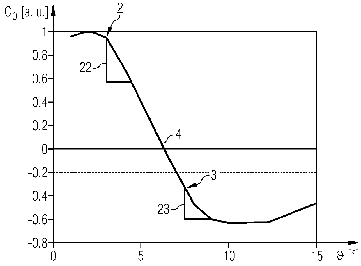
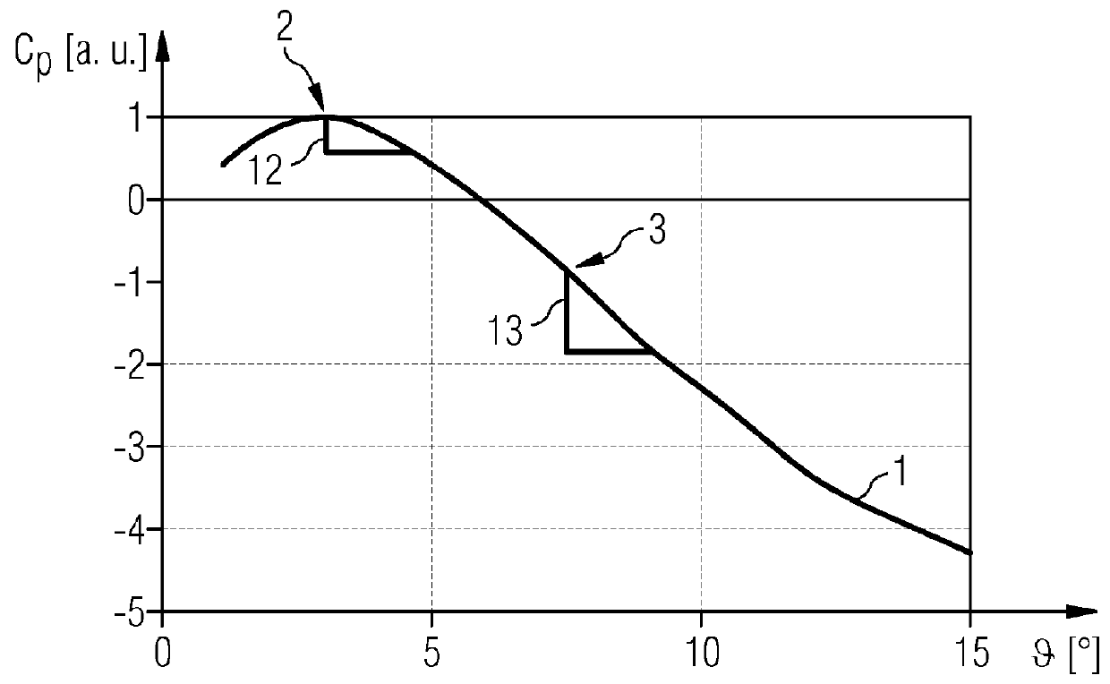
[0030]FIG. 1 schematically shows the turbine power efficiency Cp as a function of the pitch angle θ for a fixed wind speed and for a fixed rotational speed of the rotor or generator.

[0031]A wind turbine rotor blade comprises a span direction and a longitudinal axis parallel to the span. The pitch angle describes a rotation of the wind turbine rotor blade about its longitudinal axis or about its span.

[0032]In FIG. 1 the power efficiency was normalised and is plotted in arbitrary units. The curve 1, which represents the dependence of the power efficiency on the pitch angle, shows maximum power efficiency for a pitch angle of 3°. For pitch angles between 3° and about 5° the curve 1 shows a negative slope with a smaller absolute value than the slope of the curve 1 at a pitch angle between 5° and 12°.

[0033]The arrow 2 indicates the maximum power efficiency, which corresponds to an optimal pitch angle θopt, in the pr...


PUM


Abstract

A method for controlling a wind turbine with a rotor and at least one rotor blade, and a control unit are disclosed. The method is characterized in adjusting a pitch angle of the rotor blade and determining the limit of an input value based on the adjusted pitch angle, wherein the input value includes information about the turbine rotational speed.

Description

CROSS REFERENCE TO RELATED APPLICATIONS[0001]This application claims priority of European Patent Application No. 11195341.0 EP filed Dec. 22, 2011. All of the applications are incorporated by reference herein in their entirety.FIELD OF INVENTION[0002]A method for controlling a wind turbine, a control unit for controlling a wind turbine and a wind turbine are provided.BACKGROUND OF INVENTION[0003]The extreme load is in several cases the design driving factor in tower design. To improve the turbine power output it is necessary to increase the rotational speed of the turbine, both to reduce gear loads and improve aerodynamic efficiency. However, an increased rotational speed may result in higher extreme load.[0004]Turbines today have a fixed maximum speed. At this speed the extreme loads are known and used to design the turbine. The turbine controller will constantly aim to hold this speed, especially at high wind speeds.[0005]It turns out that the turbine controller has the biggest pr...

Claims


Application Information

Patent Timeline
Patent Type & Authority Patents(United States)
IPC IPC(8): F03D7/02
CPCF03D7/0224F03D7/02F03D7/0264F03D7/0276F05B2260/71F05B2270/101F05B2270/107F05B2270/32F05B2270/327F05B2270/328Y02E10/723Y02E10/72
Inventor BJERGE, MARTIN HUUSEGEDAL, PERHOEGH, GUSTAVKRISHNA, RAMAKRISHNANLAURBERG, HANS
Owner SIEMENS GAMESA RENEWABLE ENERGY AS
Why Eureka
Try Eureka