
Compression garments and method of manufacture

Inactive Publication Date: 2012-09-06
SKINS INT TRADING
View PDF17 Cites 29 Cited by
  • Summary
  • Abstract
  • Description
  • Claims
  • Application Information

AI Technical Summary

Benefits of technology

[0017]The first aspect of the invention is based on the concept of providing panels in the compression garment to represent patterns of arrangement of muscle structure. This concept takes into account that the larger, more powerful muscle groups have the most muscle fibres, but their degree of shortening is small. Examples of these muscle groups are the gluteals (gluteus maximus), the quads (quadriceps, located at the front of the thighs), the hams (hamstrings, located at the back of the thighs), the calves (located at the back of the lower leg), the traps (trapezius, located in the upper back of the torso), the lats (latissimus dorsi, mid side back of the torso) and the rectus abdominis (the front abdominals). In preferred embodiments, the first panel fully covers the muscle belly of such muscle groups. It is believed that in this way vasoconstriction of the muscle belly may be reduced and more effective compression over muscle groups with more blood supply may be effected.
[0036]It is particularly preferred that a third panel of higher elasticity is inserted on the rear of the upper body garment in the region of the wearer's spine to permit stretching and twisting.

Problems solved by technology

This alters the effect of the static compression and can create undesirable effects, in being undesirably tight or in providing more compression in the wrong places.
In turn, this can impede circulation and reduce the effect of lymphatic drainage.
Prior art compression garments do not take into consideration difference in the degree of shortening which takes place during activity and exposure to increased eccentric load (lengthening) for some muscle groups.
The illiotibial band may become tight for various reasons and the pain may be experienced down the side of the leg.
It has been found that excess pressure provided by a compression garment may cause friction of the illiotibial band over the hip and knee joint, resulting in or adding to ITBFS.

Method used


Image

  • Compression garments and method of manufacture
  • Compression garments and method of manufacture
  • Compression garments and method of manufacture

Examples


Embodiment Construction

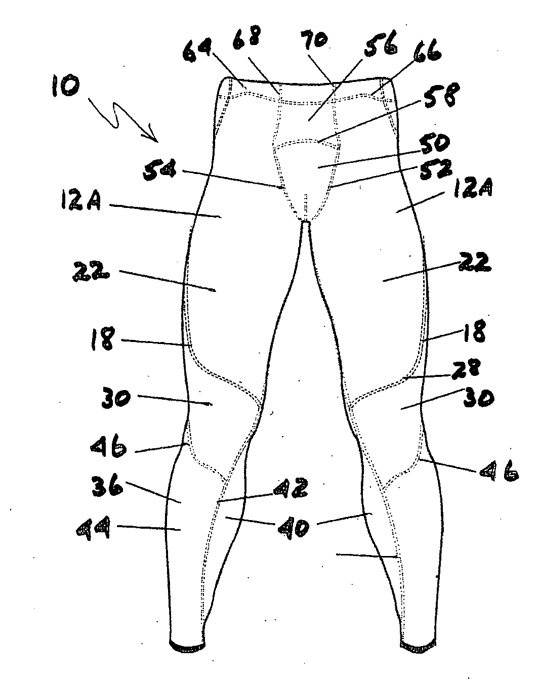
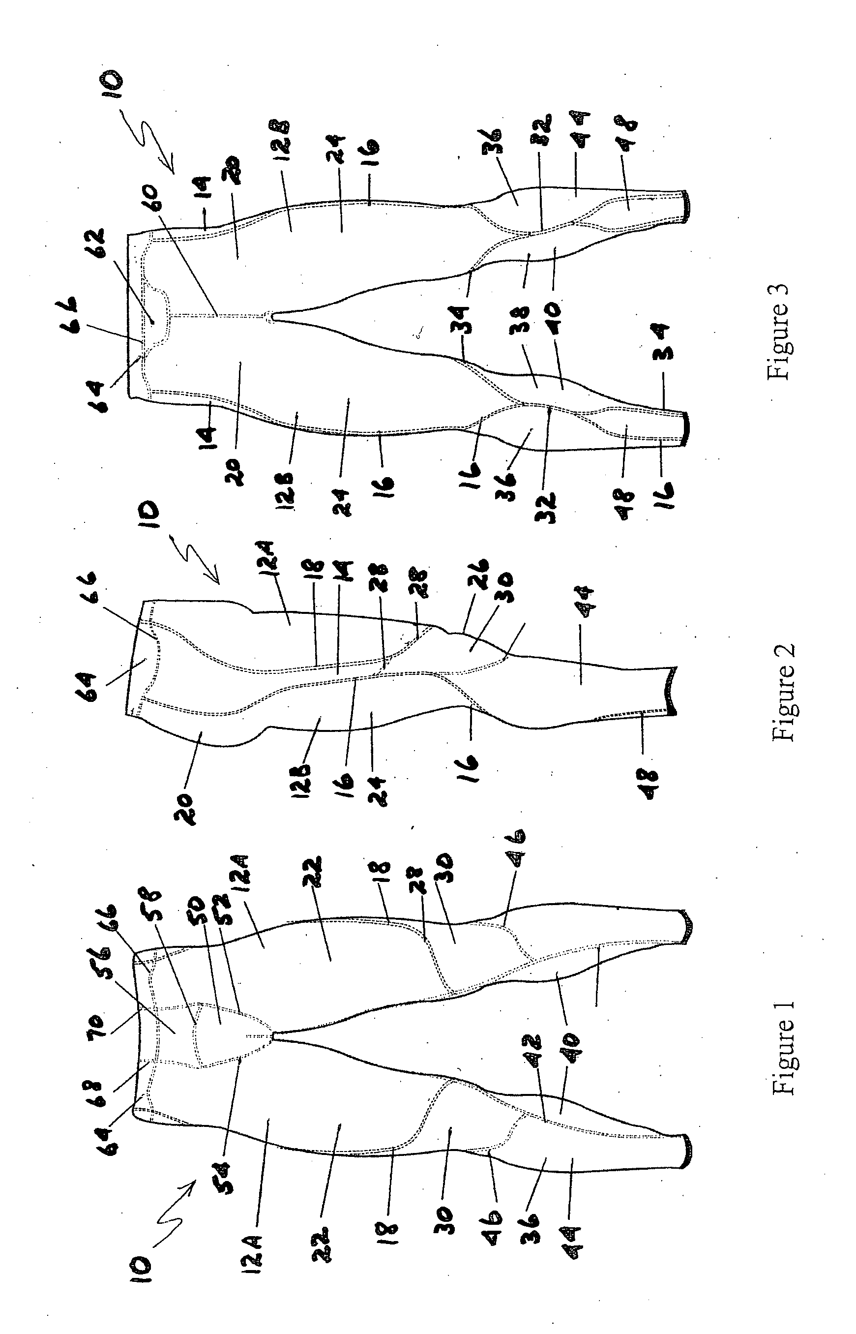
[0048]Referring first to FIGS. 1 to 3, compression garment 10 is shown as a lower body garment in the form of long tights, for clothing a body part being the lower torso, from approximately the wearer's waistline to the wearer's ankles.

[0049]Long tights 10 have first panels of stretchable material 12A and 12B and a second panel of stretchable material 14. First panel 12A is joined to second panel 14 by second seam 18 First panel 12B is joined to second panel 14 by first seam 16. Effectively, first panel 12 is divided into two parts, 12A and 12B, panel 12A covering the front of the wearer's thigh as shown in FIG. 1 and panel 12B covering the back of the wearer's thigh as shown in FIG. 3, with a seam (not shown) joining the panels 12A and 12B running along the inside thigh of the wearer.)

[0050]First panels 12A and 12B require more force to stretch and therefore are less elastic than second panel 14.

[0051]First panel 12B is adapted to support the gluteus maximus of the wearer, located ...


PUM


Abstract

This invention relates to a compression garment (10) for clothing a body part including a lower body part of a wearer. The compression garment has a first panel (12) of stretchable material joined to a second panel (14) of stretchable material by a first seam (16). The stretchable material of the second panel (14) has a higher stretch and recovery characteristic compared to the stretchable material of the first panel (12). In use, the first panel (12) of stretchable material is adapted to support a larger, more powerful muscle group than the second panel (14). The second panel (14) is joined to a third panel or the first panel (12) by a second seam (18). The second panel (14) is adapted in use to be located along a substantial part of the illiotibial band of the wearer.

Description

TECHNICAL FIELD[0001]The present invention relates to compression garments and to methods of manufacture. In particular, this invention is concerned with compression garments including upper body garments and lower body garments.BACKGROUND[0002]Prior art compression garments are generally designed to fit the body snugly, but without consideration as to the extent to which muscles increase in bulk and mass during activity. Such prior art garments can become non-static or counter-gradient in this situation. Once a person wearing a static compression garment increases muscle mass with activity, the garment can become tighter in the vicinity of the muscle, which can increase as much as 3-5% in volume. This alters the effect of the static compression and can create undesirable effects, in being undesirably tight or in providing more compression in the wrong places. In turn, this can impede circulation and reduce the effect of lymphatic drainage.[0003]Prior art compression garments do not...

Claims


Application Information

Patent Timeline
IPC IPC(8): A41D13/00A41D1/00
CPCA41D2300/22A41D2400/60A61F13/08A41D13/0015A41D31/12A41D31/185A41B9/04A41C1/18A41D13/05A41D27/00
Inventor MCLAREN, JASONHERROD, AMANDAPAYNE, BARTON
Owner SKINS INT TRADING
Learn More