Welding method and welding device

Active Publication Date: 2012-09-06
PANASONIC INTELLECTUAL PROPERTY MANAGEMENT CO LTD
View PDF55 Cites 13 Cited by
  • Summary
  • Abstract
  • Description
  • Claims
  • Application Information

AI Technical Summary

Benefits of technology

[0021]An object of the present invention is to provide a method and device for performing welding as follows. A short circuit that does not easily open is urged to open so as to reduce the frequency at which welding is unnecessarily interrupted by an overcurrent protection function. This can prevent welding defects and improve production efficiency.
[0023]This method urges the opening of a short circuit so as to reduce the frequency at which welding is unnecessarily interrupted by the overcurrent protection function. This achieves high weld quality such as the absence of welding defects, and high production efficiency such as short weld time.
[0025]This structure urges the opening of a short circuit so as to reduce the frequency at which welding is unnecessarily interrupted by an overcurrent protection function. This achieves high weld quality such as the absence of welding defects, and high production efficiency such as short weld time.
[0027]This structure urges the opening of a short circuit so as to reduce the frequency at which welding is unnecessarily interrupted by the overcurrent protection function. This achieves high weld quality such as the absence of welding defects, and high production efficiency such as short weld time.

Problems solved by technology

In the case, however, that the welding wire is made of a material not easily meltable due to its low intrinsic resistivity such as aluminum, the welding wire continues to be semi-molten even when a large current is supplied to open a short circuit.
In this case, the short circuit does not open, thus failing to create an arc.
If the short circuit does not smoothly open, welding may be interrupted either due to the buckling of the welding wire or due to the stop of the welding device in response to an overcurrent protection function.
This causes welding wire 9 to be pushed deeply into the weld pool of base material 12, making it much more difficult to open the short circuit.
Failing to open the short circuit during the predetermined period causes the overcurrent protection function to come into operation, and forcefully terminates welding device 1.
This often damages base material 12, causes quality issues such as welding defects, or reduces production efficiency.

Method used


Image

  • Welding method and welding device
  • Welding method and welding device
  • Welding method and welding device

Examples


first exemplary embodiment

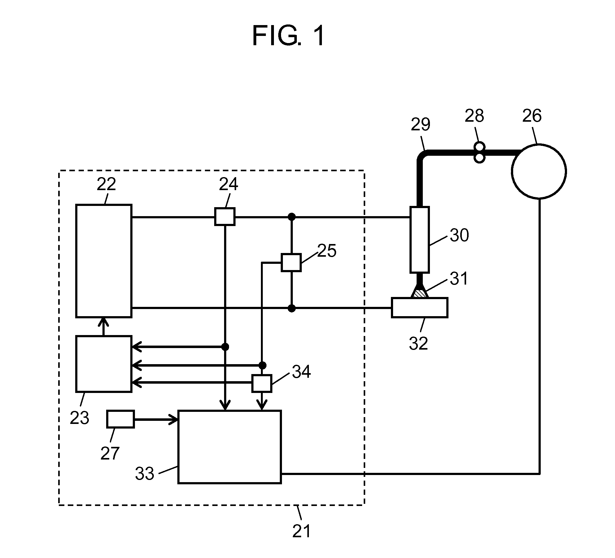
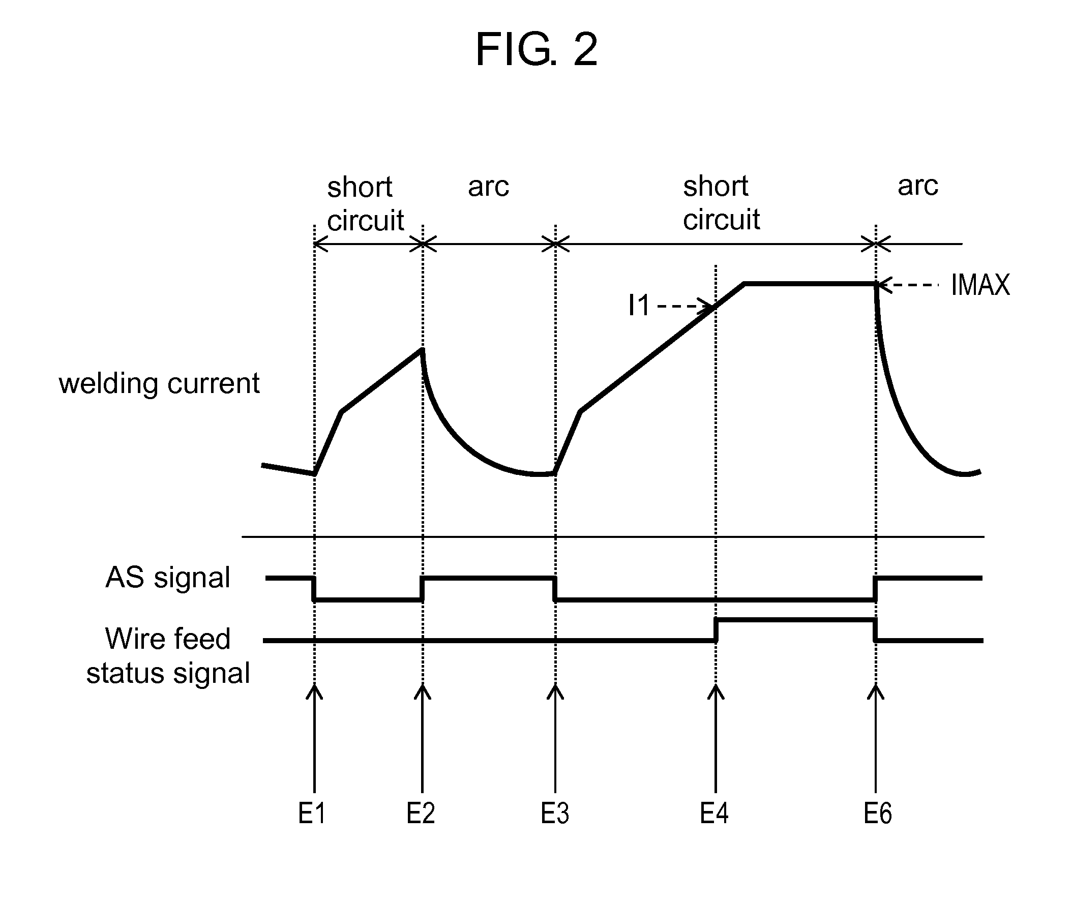
[0037]FIG. 1 shows a schematic configuration of welding device 21 according to a first exemplary embodiment of the present invention. FIGS. 2 and 3 show temporal changes of a welding current, an AS signal which indicates an arc state and a short-circuit state, and a wire feed status signal in the welding device.

[0038]As an example of a welding device, a consumable electrode arc welding device is described as follows, which performs welding by alternately repeating short circuits and arcs. The operation of welding device 21 shown in FIG. 1 is described with reference to FIGS. 2 and 3.

[0039]In welding device 21 shown in FIG. 1, welding output unit 22 provides a welding output. Output controller 23 controls welding output unit 22. Current detector 24 detects a welding current. Voltage detector 25 detects a welding voltage. Feeding motor 26 feeds welding wire 29. Current setting unit 27 sets a threshold for the welding current. Feed roller 28 feeds, via welding torch 30, welding wire 29...

second exemplary embodiment

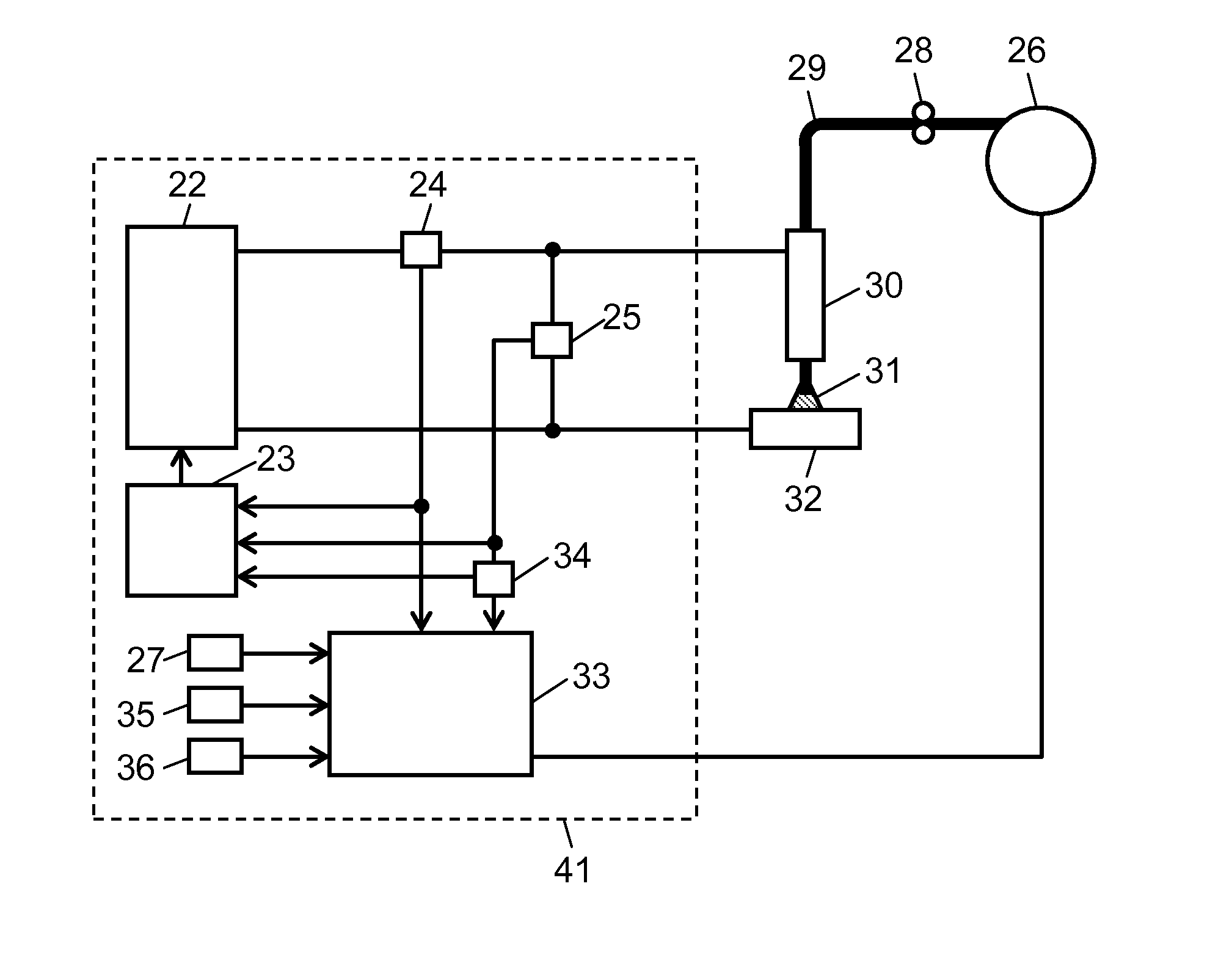
[0070]Welding device 41 and its operation according to a second exemplary embodiment of the present invention is described with reference to FIGS. 4 to 6. FIG. 4 is a schematic configuration of welding device 41. FIGS. 5 and 6 show temporal changes of a welding current, an AS signal which indicates an arc state and a short-circuit state, and a wire feed status signal in the welding device according to the second exemplary embodiment.

[0071]The main difference of welding device 41 of FIG. 4 from welding device 21 of FIG. 1 is to include elapsed-time setting unit 35 and time keeper 36, which will be described later.

[0072]As shown in FIG. 4, elapsed-time setting unit 35, which may be composed of a CPU, sets a first predetermined time T1 as an elapsed-time threshold since the welding current reached the first current value I1. Time keeper 36, which may also be composed of a CPU, counts the time since the welding current reached the first current value I1.

[0073]Wire feed controller 33 con...


PUM

PropertyMeasurementUnit
Timeaaaaaaaaaa
Currentaaaaaaaaaa

Abstract

In a method and device for performing welding, after the welding current reaches a first current value during a short circuit, the feeding of the welding wire is stopped, slowed down, or moved backward. As a result, the opening of a short circuit is urged to reduce the frequency at which welding is unnecessarily interrupted by an overcurrent protection function. This achieves high weld quality such as the absence of welding defects, and high production efficiency.

Description

TECHNICAL FIELD[0001]The present invention relates to a method and device for performing welding by feeding a welding wire and alternately repeating short circuits and arcs.BACKGROUND ART[0002]In a conventional device for performing welding by automatically feeding a welding wire and alternately repeating short circuits and arcs, a short circuit is urged to open by supplying a large current to increase the short-circuit current with time until the short circuit opens and an arc occurs.[0003]In the case, however, that the welding wire is made of a material not easily meltable due to its low intrinsic resistivity such as aluminum, the welding wire continues to be semi-molten even when a large current is supplied to open a short circuit. In this case, the short circuit does not open, thus failing to create an arc.[0004]If the short circuit does not smoothly open, welding may be interrupted either due to the buckling of the welding wire or due to the stop of the welding device in respon...

Claims


Application Information

Patent Timeline
IPC IPC(8): B23K9/10
CPCB23K9/073B23K9/09B23K9/124
Inventor TANAKA, YOSHIAKIMATSUMOTO, KAZUNORISATO, KIMIYANAKAGAWA, AKIRAYUZAWA, HIROKIIHARA, HIDEKI
Owner PANASONIC INTELLECTUAL PROPERTY MANAGEMENT CO LTD
Why Eureka
Try Eureka