High efficiency proportional neutron detector with solid liner internal structures

a neutron detector and internal structure technology, applied in the field of neutron detectors, can solve the problems of increasing the need for warhead disassembly, difficult problem, and difficulty in snm detection and characterization, and achieve the effects of improving detection efficiency, reducing costs, and high cos

Active Publication Date: 2012-09-06
UT BATTELLE LLC
View PDF1 Cites 38 Cited by
  • Summary
  • Abstract
  • Description
  • Claims
  • Application Information

AI Technical Summary

Benefits of technology

[0007]Moderator units can be incorporated into a neutron detector to provide improved detection efficiencies and/or to determine neutron energy spectrum. Gas-based proportional response from the neutron detectors can be employed for special nuclear material (SNM) detection. This neutron detector can provide similar performance to 3He-based detectors without requiring 3He and without containing toxic, flammable, or high-pre

Problems solved by technology

The unambiguous detection and characterization of special nuclear materials (SNM), particularly shielded highly enriched uranium at standoff distances and weapons grade plutonium, is a challenging problem.
Recently, that problem has become even more acute due to the worldwide shortage of 3He—the neutron

Method used


Image

  • High efficiency proportional neutron detector with solid liner internal structures
  • High efficiency proportional neutron detector with solid liner internal structures
  • High efficiency proportional neutron detector with solid liner internal structures

Examples


first embodiment

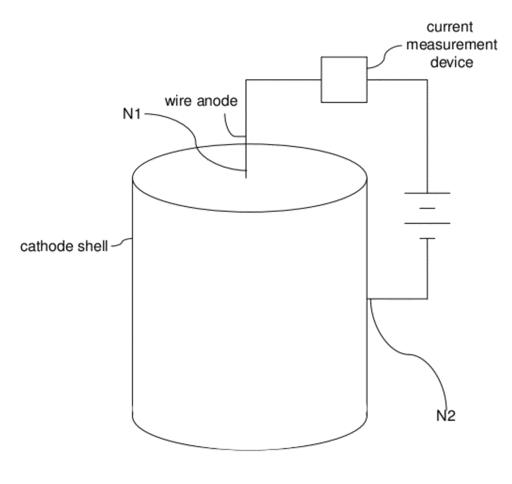
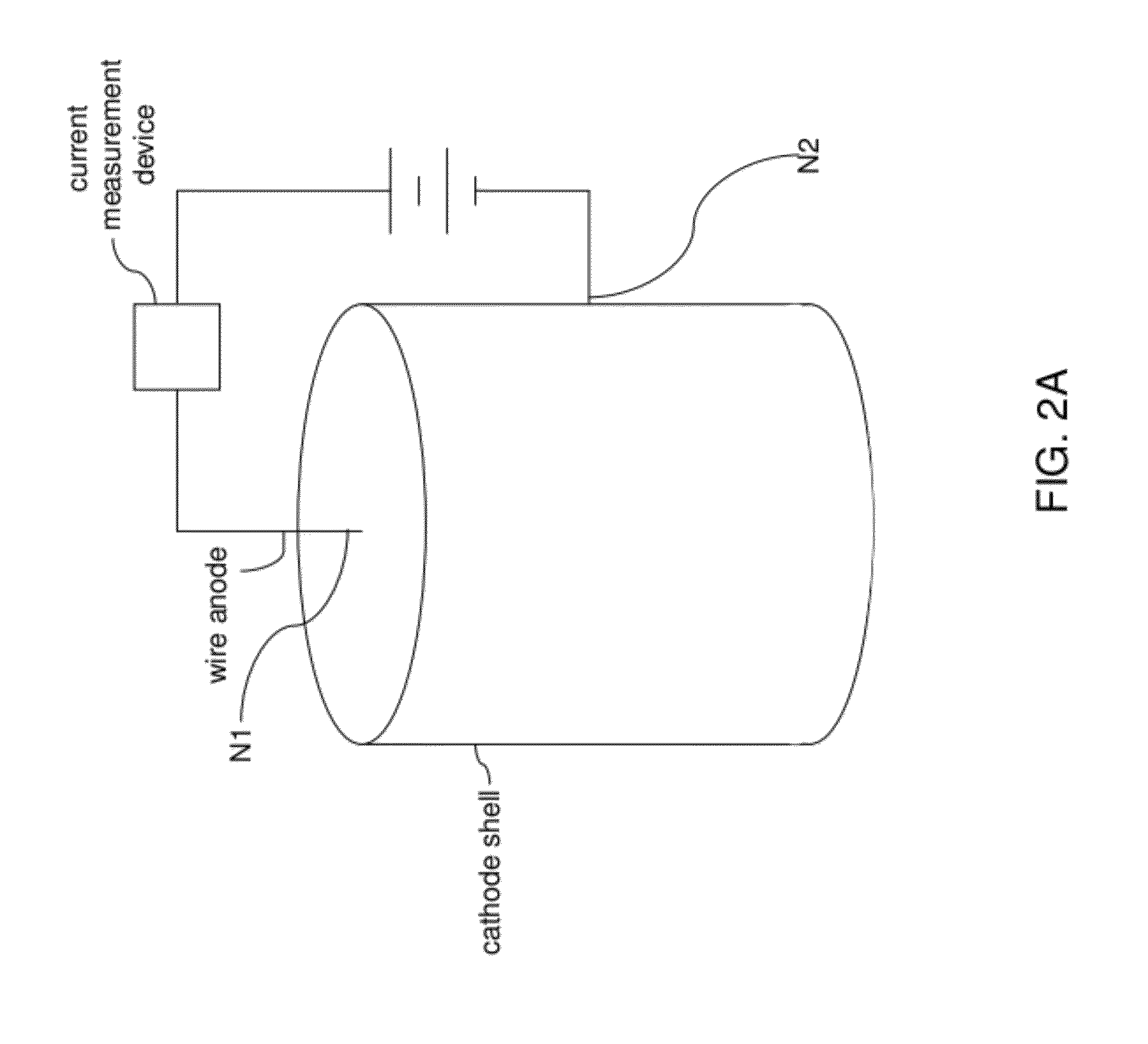
[0049]Referring to FIGS. 2A, 2B, and 2C, an exemplary neutron detector including a single neutron detector unit is shown according to the present disclosure. FIG. 2A shows the overall configuration of the exemplary neutron detector, FIG. 2B shows a horizontal cross-sectional area of a first exemplary detector unit, and FIG. 2C shows a side view of the first exemplary detector unit excluding a cylindrical conductive cathode.

[0050]The exemplary neutron detector includes a direct current (DC) voltage supply source, which can be a battery, a series connection of batteries, or any electrical circuit configured to provide a stable and constant direct current (DC) voltage bias. The DC voltage supply source is connected across a positive voltage supply node N1 and a negative voltage supply node N2 of the first exemplary detector unit. The positive voltage supply node N1 can be a portion of a wire anode that protrudes from an enclosure of the first exemplary detector unit, and the negative v...

second embodiment

[0095]Referring to FIGS. 8A and 8B, an exemplary neutron detector unit according to the present disclosure is illustrated in various views. FIG. 8A includes a top-down view in the upper left corner, and a front view in the lower left corner. A magnified view of a portion of the hexagonal array of channels is shown in an inset. FIG. 8B is a further magnified view of the hexagonal array of channels. This exemplary neutron detector unit is another panel-type neutron detector unit.

[0096]This panel-type neutron detector unit of FIGS. 8A and 8B can replace the single tube neutron detector unit of FIG. 2A, and can be connected to a DC voltage supply source and a current measurement device to form a panel-type neutron detector. Each wire anode among the plurality of cylindrical neutron detector units is electrically connected to a positive voltage supply node of the DC voltage supply source, and each tubular conductive cathode is electrically connected to a negative voltage supply node of t...


PUM


Abstract

A tube-style neutron detector, a panel-style neutron detector incorporating a plurality of tube-style neutron detectors, and a panel-style neutron detector including a plurality of anode wires are provided. A plurality of channels is provided in a neutron detector such that each channel has an inner surface of a coating layer including a neutron-absorbing material. A wire anode is provided at end of each channel so that electrons generated by a charged daughter particle generated by a neutron are collected to detect a neutron-matter interaction. Moderator units can be incorporated into a neutron detector to provide improved detection efficiencies and/or to determine neutron energy spectrum. Gas-based proportional response from the neutron detectors can be employed for special nuclear material (SNM) detection. This neutron detector can provide similar performance to 3He-based detectors without requiring 3He and without containing toxic, flammable, or high-pressure materials.

Description

RELATED APPLICATIONS[0001]This application claims the benefit of priority of the U.S. provisional application 61 / 447,756 filed on Mar. 1, 2011.STATEMENT REGARDING FEDERALLY SPONSORED RESEARCH OR DEVELOPMENT[0002]This invention was made with government support under Contract No. DE-AC05-00OR22725 awarded by the U.S. Department of Energy. The government has certain rights in this invention.FIELD OF THE INVENTION[0003]The present invention relates to neutron detectors, and particularly to neutron detectors employing a coating layer of a neutron-absorbing material, and methods of operating the same.BACKGROUND OF THE INVENTION[0004]The unambiguous detection and characterization of special nuclear materials (SNM), particularly shielded highly enriched uranium at standoff distances and weapons grade plutonium, is a challenging problem. Recently, that problem has become even more acute due to the worldwide shortage of 3He—the neutron converter isotope for the leading SNM neutron detectors.[...

Claims


Application Information

Patent Timeline
IPC IPC(8): G01T3/00
CPCG01T3/008
Inventor BROWN, GILBERT M.HOLCOMB, DAVID EUGENEKISNER, ROGER ALLEN
Owner UT BATTELLE LLC
Why Eureka
Try Eureka