Opening seal for automobiles and method of preparing the same

Active Publication Date: 2012-09-06
NISHIKAWA RUBBER
View PDF4 Cites 7 Cited by
  • Summary
  • Abstract
  • Description
  • Claims
  • Application Information

AI Technical Summary

Benefits of technology

[0038]The leaned straight line as extended intersects the hollow seal member on a position on the internal circumference side of a door (on the connecting wall side from the opening part side of the installation base member) compared with the prior art (FIG. 9) in which the leaned straight line as extended intersects hollow seal member on a position on the outer circumference side. Accordingly, contracting force functions within a smaller domain of the hollow seal member when the opening seal for automobiles is assembled on a corner part on the body side of the automobile, thereby preventing generation of folding wrinkles.
[0039]Further, by leaning the straight line which connects the position of the non-thermo-fusible yarn on the outer-cabin side and the position of the non-thermo-fusible yarn on the inner-cabin side, fastening force of the installation base member on the flange from the inner-cabin side wall side is increased, which enables the protuberance provided on the inner-cabin side wall side to hold the flange sufficiently.
[0040]Such a structure enables stable assembly of the opening seal for automobiles on the corner part on the body side of the automobile and keeps the opening seal stably assembled after the assembly.
[0041]In addition, according to the present invention, the non-thermo-fusible yarn on the outer-cabin side is provided from the bending end position, not bending start position forming the shoulder on the outer-cabin side of the wire body which is bent roughly in U-shape. Accordingly, the non-thermo-fusible yarn on the outer-cabin side is provided on the outer-cabin side wall side of the installation base member, changed from the connecting wall side. Such a structure improves balance when connecting the wire body and effectively controls unnecessary ex

Problems solved by technology

Such problems are remarkable when

Method used


Image

  • Opening seal for automobiles and method of preparing the same
  • Opening seal for automobiles and method of preparing the same
  • Opening seal for automobiles and method of preparing the same

Examples


Example

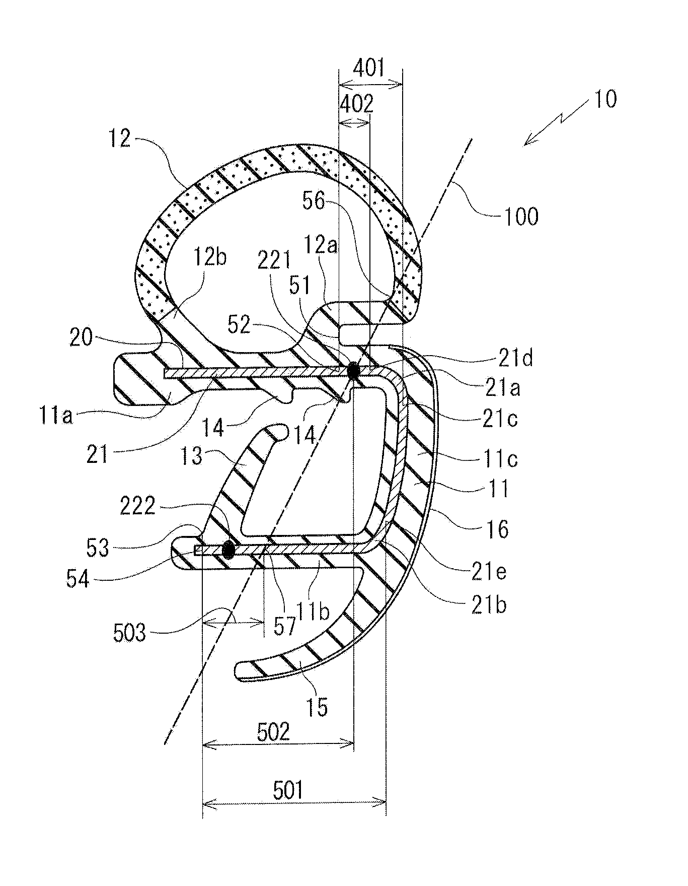
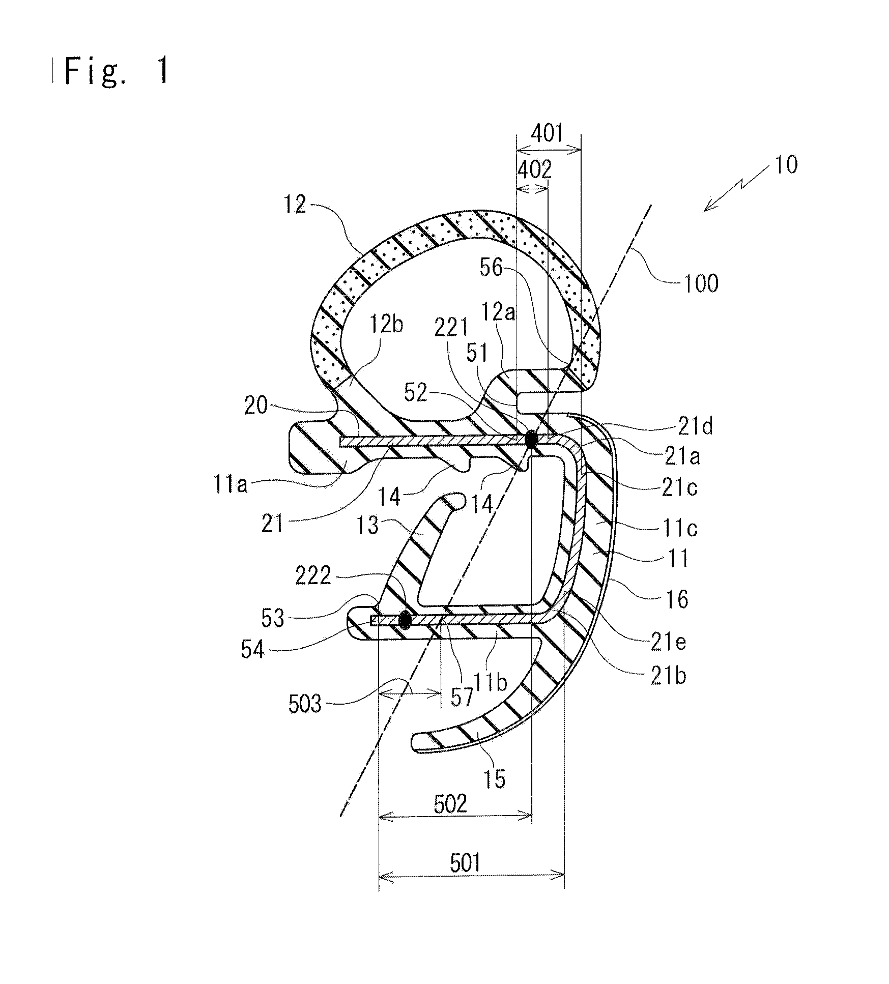
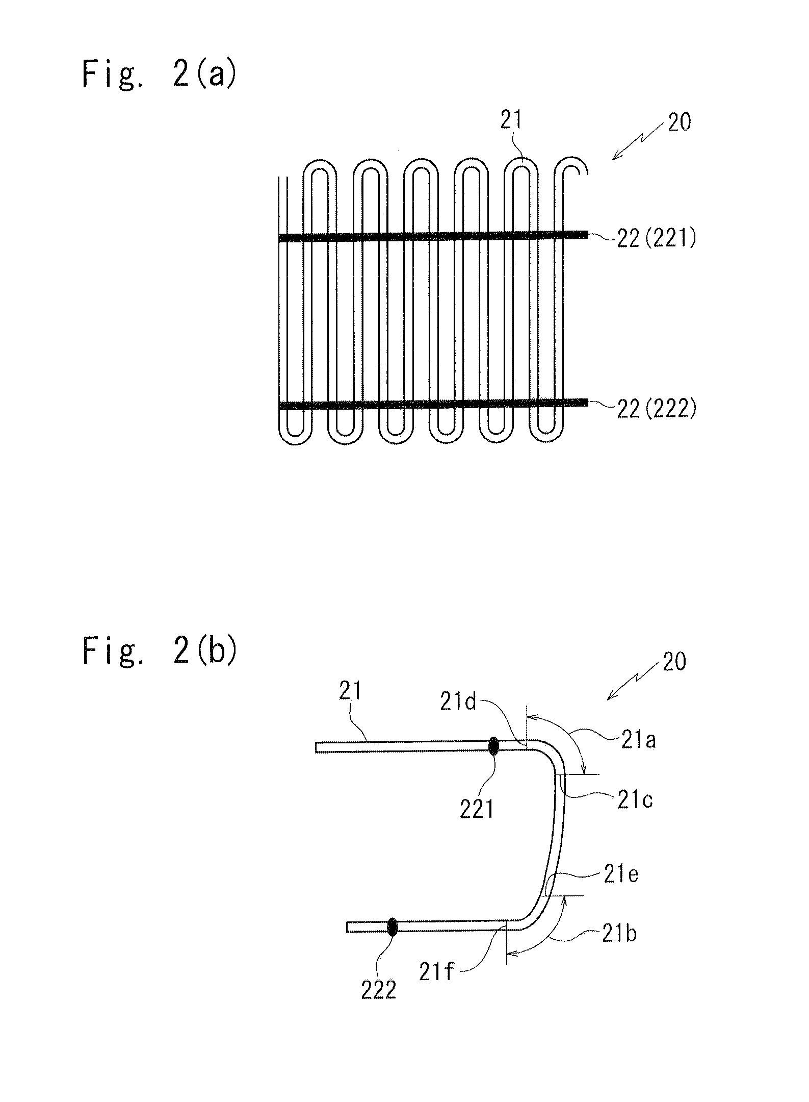
[0060]Referring to FIG. 1 and FIG. 2, an opening seal 10 for automobiles according to an embodiment of the present invention will be described. FIG. 1 is a cross section showing an opening seal 10 for automobiles according to an embodiment of the present invention and FIG. 2 shows a cross section of a wire core 20 shown in FIG. 1. When constituents or items correspond to those in prior arts, the same symbols are used.

[0061]The opening seal 10 for automobiles according to the embodiment of the present invention mainly comprises: an installation base member 11; a hollow seal member 12; a protuberance 13; and a wire core 20.

[0062]The installation base member 11 is cross section roughly U-shaped, including an outer-cabin side wall 11a, an inner-cabin side wall 11b and a connecting wall 11c connecting the side walls 11a, 11b. In the same manner as FIG. 8 and FIG. 9, the installation base member 11 is installed on a flange 3 installed along a periphery of a door 2 opening part of a body 1...


PUM

PropertyMeasurementUnit
Specific gravityaaaaaaaaaa

Abstract

In a wire core 20 embedded in an opening seal for automobiles, a non-thermo-fusible yarn221 on the outer-cabin side is provided in a range 401 from a bending start position 21c forming a shoulder 21a on the outer-cabin side of a wire body 21 which is bent roughly in U-shape to a position 52 determined by offsetting a point 51 on a door internal circumference side of a base 12a of a hollow seal member 12 on the inner side whereas a non-thermo-fusible yarn 222 on the inner-cabin side is provided in a range 501 from a bending start position 21e forming a shoulder 21b on the inner-cabin side of the wire body 21 to a position 54 determined by offsetting a point 53 on an opening edge side on an inner-cabin side wall 11b of a base of a protuberance 13 with respect to the wire body 21.

Description

CROSS-REFERENCE TO RELATED APPLICATION[0001]This application claims the benefit under 35 USC 119 of JP Patent Application JP 2011-043851 filed Mar. 1, 2011, the entire disclosure of which is incorporated herein by reference.BACKGROUND OF THE INVENTION[0002]The present invention relates to opening seals for automobiles and method of preparing the same having wire core embedded in installation base members thereof for increasing rigidity, which are installed along peripheries of door opening parts of automobile bodies for sealing openings between bodies and doors by making elastic contact with the doors when the doors are closed.[0003]As shown in FIG. 8 and FIG. 9, an opening seal 10 for automobiles having a wire core 20 embedded therein has been well-known, which is mounted on a flange 3 installed along a periphery of a door 2 opening part on an automobile body 1 side for making elastic contact with the door 2 when the door 2 is closed to seal an opening between the body 1 and the do...

Claims


Application Information

Patent Timeline
IPC IPC(8): B60J10/08B29C47/02B29L9/00B60R13/06
CPCB60J10/0011B60J10/0031Y10S277/921B60J10/081B60J10/0065B60J10/00B60R13/06B60J10/24B60J10/84B60J10/18B60J10/32
Inventor NISHIMOTO, YOSHITAKANISHIKAWA, SHINJIMCCABE, BRIAN
Owner NISHIKAWA RUBBER
Why Eureka
Try Eureka