
Apparatuses and methods for reducing power in driving display panels

a technology for reducing power and display panels, applied in lighting apparatuses, instruments, light sources, etc., can solve the problems of high power consumption, system end up with a net loss of only about half the energy required, and still high energy consumption, and achieve the effect of saving energy

Inactive Publication Date: 2012-09-06
INTEGRATED DEVICE TECH INC
View PDF5 Cites 4 Cited by
  • Summary
  • Abstract
  • Description
  • Claims
  • Application Information

AI Technical Summary

Benefits of technology

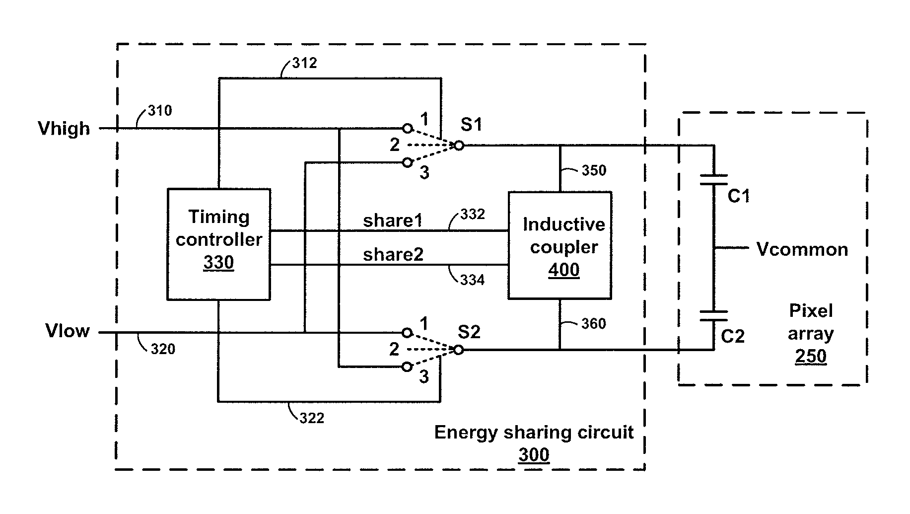
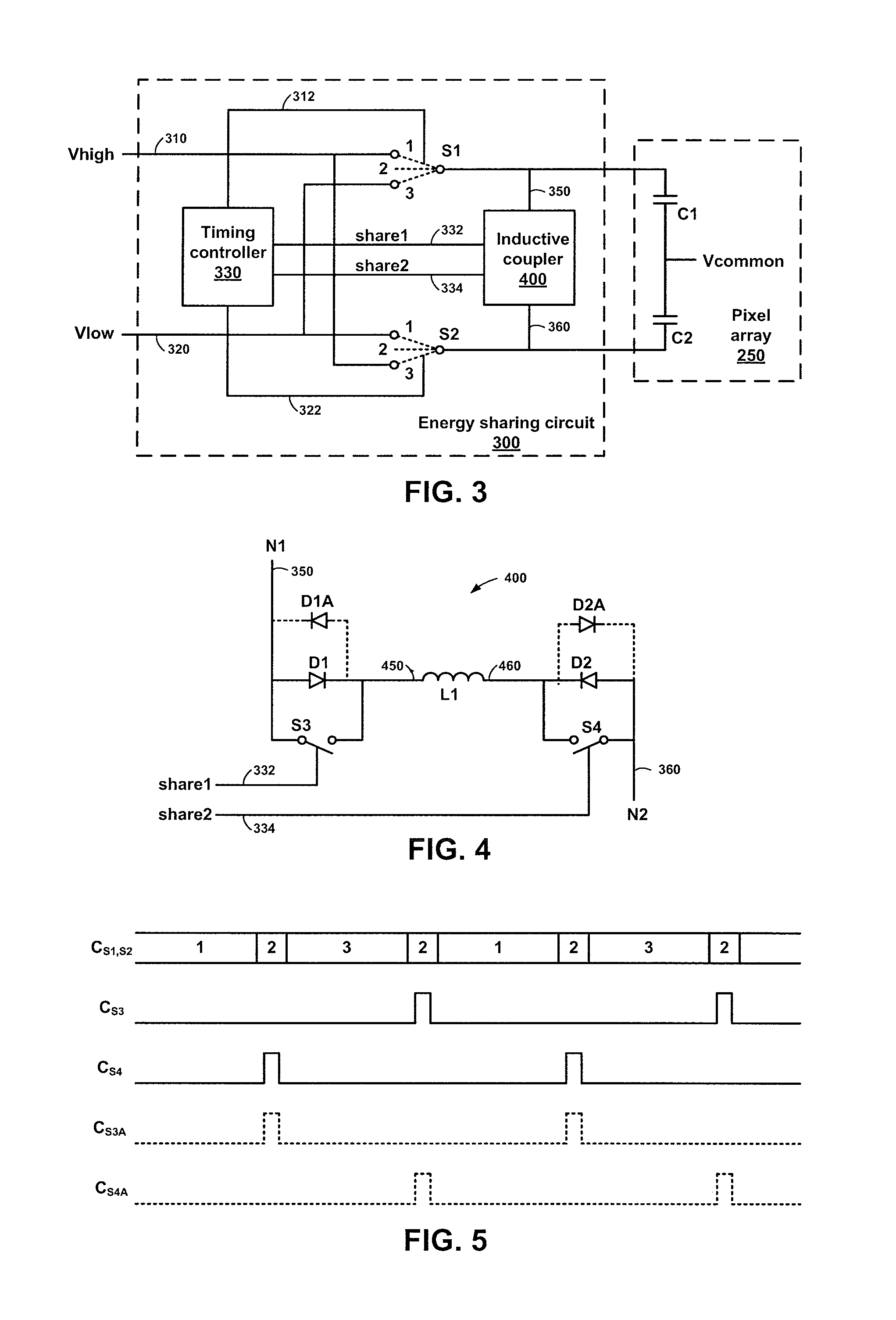
The present invention provides new energy sharing circuits that reduce power more than conventional charge sharing circuits. The circuits include a first source line, a second source line, and an inductive coupler for selectively coupling the two lines through a forward biased diode and an inductor connected in series. The circuits also include high and low switches for selectively coupling high and low voltages to the source lines, and a diode block for preventing energy from returning to the source lines. The method allows for energy to be inductively moved from one source line to another, resulting in a higher voltage on the first source line and a lower voltage on the second source line. The circuits and method provide more efficient energy sharing and reduced power consumption.

Problems solved by technology

Since these control lines are operated at high frequency the resulting power dissipation is inconveniently large, which may result in self-heating and high power consumption.
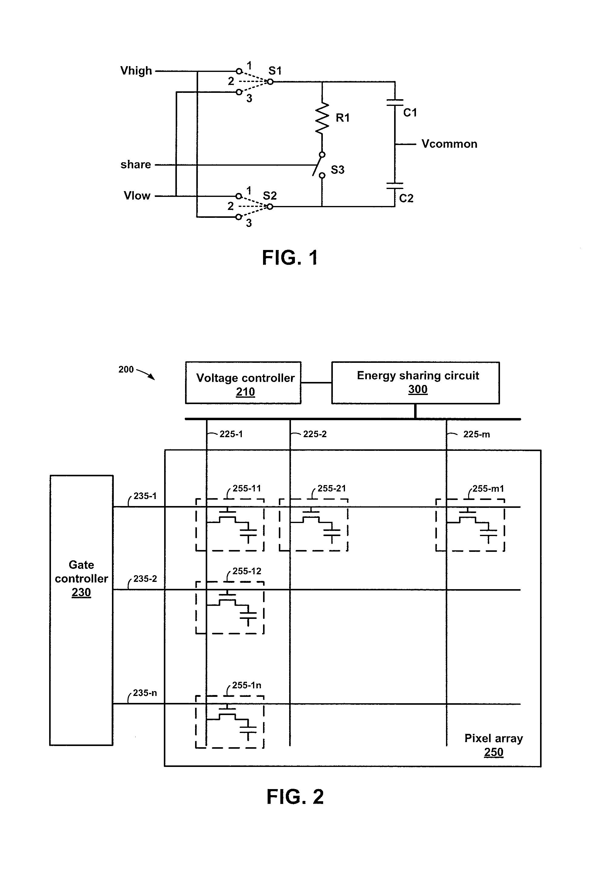
As a result, the system ends up with a net loss of only about half the energy required if the capacitor ends are not shorted through the resistor R1.
However, energy consumption can still be high and the inventors have appreciated that there is a need to further reduce the energy required to drive LCD panels.

Method used


Image

  • Apparatuses and methods for reducing power in driving display panels
  • Apparatuses and methods for reducing power in driving display panels
  • Apparatuses and methods for reducing power in driving display panels

Examples


Embodiment Construction

[0027]In the following description, elements, circuits, and functions may be shown in block diagram form in order not to obscure the present invention in unnecessary detail. Conversely, specific implementations shown and described are exemplary only and should not be construed as the only way to implement the present invention unless specified otherwise herein. Additionally, block definitions and partitioning of logic between various blocks is exemplary of a specific implementation. It will be readily apparent to one of ordinary skill in the art that the present invention may be practiced by numerous other partitioning solutions. For the most part, details concerning timing considerations and the like have been omitted where such details are not necessary to obtain a complete understanding of the present invention and are within the abilities of persons of ordinary skill in the relevant art.

[0028]Furthermore, in this description of embodiments of the invention, reference is made to ...


PUM


Abstract

Energy sharing circuits and related methods are disclosed herein. A high voltage can be selectively coupled to a first source line and a low voltage can be selectively coupled to a second source line during a first time period. During a subsequent time period, a first coupling switch is activated to inductively couple the first source line to the second source line and diode block the second source line from the first source line. During a subsequent time period, the low voltage is selectively coupled to the first source line and the high voltage is selectively coupled to the second source line. During a subsequent time period, a second coupling switch is activated to inductively couple the second source line to the first source line and diode block the first source line from the second source line.

Description

TECHNICAL FIELD[0001]Embodiments of the present disclosure relate generally to power reduction for driving display panels and, more particularly, to apparatuses and methods related to energy sharing for signals that drive display panels.BACKGROUND[0002]Level shifters are often required for a Liquid Crystal Display (LCD) panel to control the voltage and charge on control lines for the LCD panel. Drivers may reverse the voltage on the control lines, which include a distributed capacitive load. In general, each control line is driven from a high power supply to a low power supply, through a switch. Since these control lines are operated at high frequency the resulting power dissipation is inconveniently large, which may result in self-heating and high power consumption.[0003]However, since the control lines are switched in pairs, each switching to the voltage of the other control line in the pair, there is a possibility to save some of the energy by connecting the two distributed capac...

Claims


Application Information

Patent Timeline
Patent Type & Authority Applications(United States)
IPC IPC(8): H05B37/00
CPCG09G3/3696G09G2330/024G09G3/3688G09G3/3614G09G3/3648G09G2330/028
Inventor BROKAW, A. PAULHER, JUNEBARROW, JEFFREY G.
Owner INTEGRATED DEVICE TECH INC
Learn More