Zoom lens and image pickup apparatus having the same

a pickup apparatus and zoom lens technology, applied in the field of zoom lenses, can solve the problems of insufficient aberration correction at the telephoto end, failure to achieve high performance and small size at the same time, and achieve the effect of well-corrected chromatic aberration and high performan

Inactive Publication Date: 2012-09-06
CANON KK
View PDF3 Cites 6 Cited by
  • Summary
  • Abstract
  • Description
  • Claims
  • Application Information

AI Technical Summary

Benefits of technology

[0010]The present invention can provide a small, light-weight zoom lens having high performance with well-corrected chromatic aberration in the telephoto zoom range while having a zoom ratio as high as or higher than 15.

Problems solved by technology

However, in the zoom lenses disclosed as numerical embodiments in Japanese Patent Application Laid-Open Nos. 2004-109993 and 2009-037036, the dispersion of the positive lenses in the first lens unit is not small and the refractive index thereof is not sufficiently high, resulting in insufficient correction of aberrations at the telephoto end and failing to achieve high performance and small size at the same time.

Method used


Image

  • Zoom lens and image pickup apparatus having the same
  • Zoom lens and image pickup apparatus having the same
  • Zoom lens and image pickup apparatus having the same

Examples


first embodiment

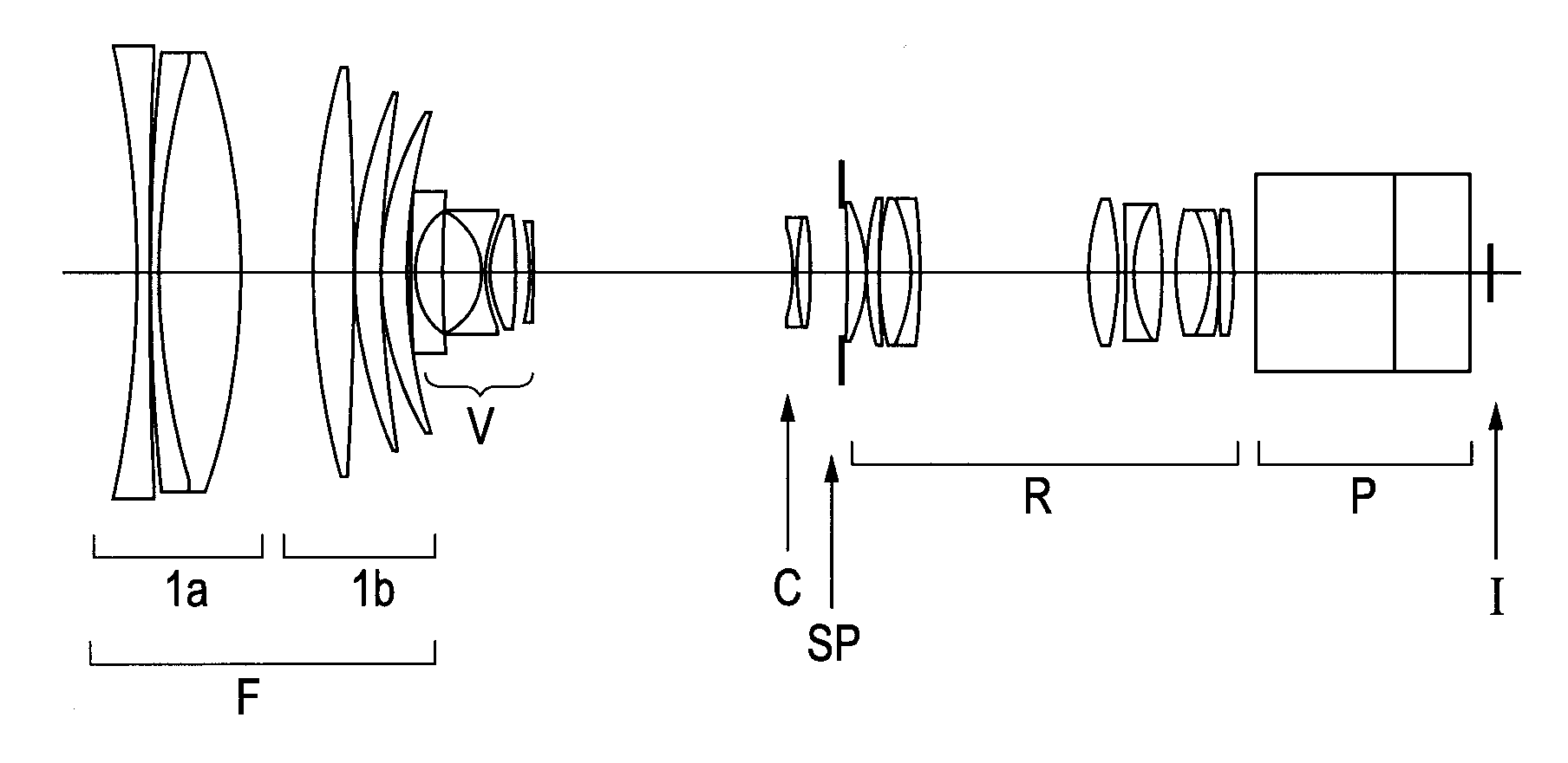
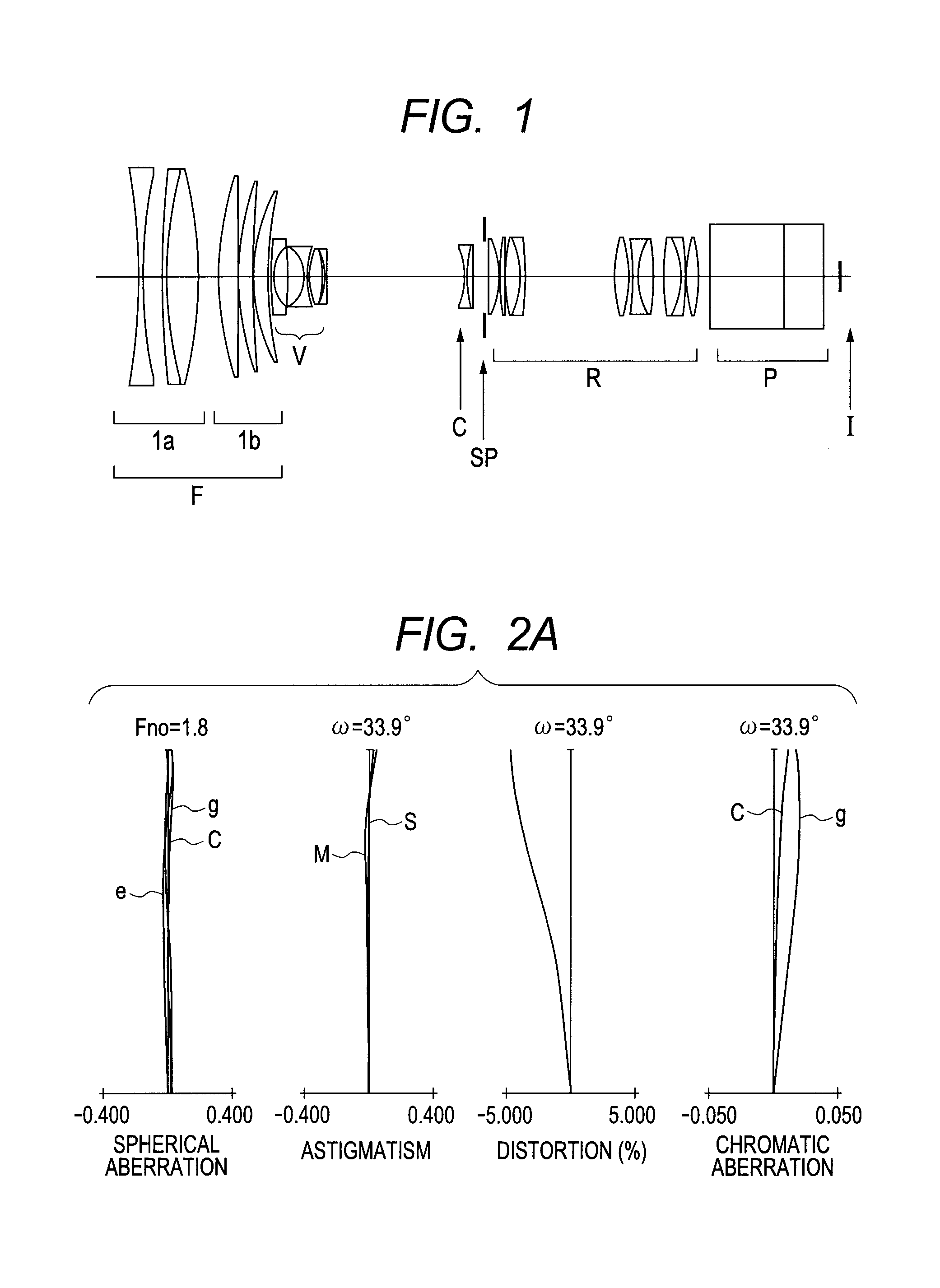
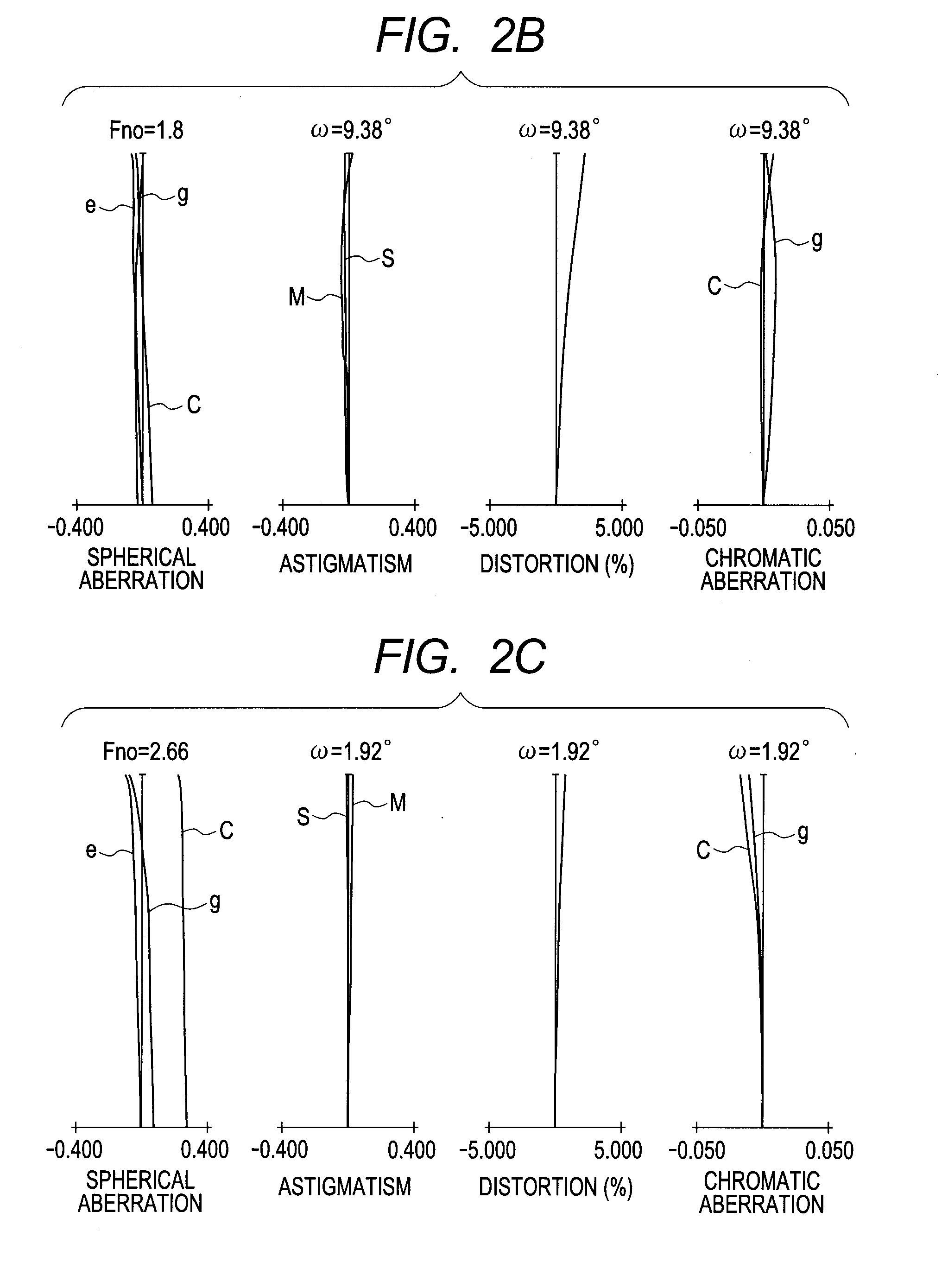
[0069]FIG. 1 is a cross sectional view of a zoom lens according to numerical embodiment 1 as a first embodiment of the present invention in the state at the wide angle end. FIGS. 2A, 2B and 2C are aberration diagrams of numerical embodiment 1 respectively at the wide angle end, at a focal length f of 33.29 mm and at the telephoto end. In the aberration diagrams, curves “e” represent aberrations with respect to the e-line, curves “g” represent aberrations with respect to the g-line, curves represent aberrations with respect to the C-line, curves “M” represent aberrations in meridional image plane, and curves “S” represent aberrations in sagittal image planes. This also applies to all the embodiments described in the following.

[0070]As shown in FIG. 1, the zoom lens according to this embodiment has a front lens unit F having a positive refractive power, which constitutes the first lens unit, a variator V having a negative refractive power for varying magnification (moving for varying ...

second embodiment

[0074]FIG. 3 is a cross sectional view of a zoom lens according to numerical embodiment 2 as a second embodiment of the present invention in the state at the wide angle end. FIGS. 4A, 4B and 4C are aberration diagrams of numerical embodiment 2 respectively at the wide angle end, at a focal length f of 32.48 mm and at the telephoto end.

[0075]As shown in FIG. 3, the zoom lens according to this embodiment has a front lens unit F having a positive refractive power, which constitutes the first lens unit, a variator V having a negative refractive power for varying magnification, which constitutes the second lens unit, and a compensator C having a negative refractive power, which constitutes the third lens unit. The first lens unit F includes a sub lens unit 1a which is located closest to the object side and does not move for varying magnification or for focusing and a positive sub lens unit 1b which does not move for varying magnification but moves for focusing. The variator V moves monot...

third embodiment

[0078]FIG. 5 is a cross sectional view of a zoom lens according to numerical embodiment 3 as a third embodiment of the present invention in the state at the wide angle end. FIGS. 6A, 6B and 6C are aberration diagrams of numerical embodiment 3 respectively at the wide angle end, at a focal length f of 30.45 mm and at the telephoto end.

[0079]As shown in FIG. 5, the zoom lens according to this embodiment has a front lens unit F having a positive refractive power, which constitutes the first lens unit, a variator V having a negative refractive power for varying magnification, which constitutes the second lens unit, and a compensator C having a negative refractive power, which constitutes the third lens unit. The first lens unit F includes a sub lens unit 1a which is located closest to the object side and does not move for varying magnification or for focusing and a positive sub lens unit 1b which does not move for varying magnification but moves for focusing. The variator V moves monoto...


PUM


Abstract

A zoom lens includes, in order from object side, a positive first lens unit which does not move for varying magnification, a negative second lens unit which moves for varying magnification, a negative third lens unit which moves for varying magnification, and a positive fourth lens unit which does not move for varying magnification, wherein the first lens unit includes a positive lens which satisfies the following conditions: 70<νp<85; 2.31<Np+0.01×νp<2.58; and 1.6<Np<1.85, where Np is refractive index of the positive lens, and νp is Abbe constant of the positive lens, and 1.25<|fp / fna|<1.7 is satisfied, where fp is focal length of the positive lens, and fna is combined focal length of negative lenses in the first lens unit defined by the equation:fna=1∑i=1n1fni,where n is a number of the negative lenses in the first lens unit, and fni is focal length of the i-th negative lens.

Description

BACKGROUND OF THE INVENTION[0001]1. Field of the Invention[0002]The present invention relates to a zoom lens which is suitable for use in a TV camera, a video camera, a still camera and a digital camera, in particular to a small, light-weighted zoom lens which has excellent performance with good chromatic aberration characteristics at the telephoto end, while having a high zoom ratio higher than 15. The present invention also relates to an image pickup apparatus having such a zoom lens.[0003]2. Description of the Related Art[0004]Heretofore, there have been developed many zoom lenses composed of four lens units including in order from the object side a first lens unit having a positive refractive power which does not move for zooming, a second lens unit having a negative refractive power for varying magnification, a third lens unit having a negative refractive power for correcting image plane variation due to the varying of the magnification, and a fourth lens unit having a positive...

Claims


Application Information

Patent Timeline
Patent Type & Authority Applications(United States)
IPC IPC(8): G02B15/14
CPCG02B15/17G02B15/144109
Inventor SAKAMOTO, MASARU
Owner CANON KK
Why Eureka
Try Eureka