Lift-Type Vertical Axis Turbine

a vertical axis turbine and lift-type technology, which is applied in vessel construction, renewable energy generation, greenhouse gas reduction, etc., can solve the problems of low overall low efficiency of towers, and low power efficiency of turbines

Inactive Publication Date: 2012-09-06
LUX
View PDF3 Cites 7 Cited by
  • Summary
  • Abstract
  • Description
  • Claims
  • Application Information

AI Technical Summary

Benefits of technology

[0021]There may be provided a weight member of increased mass supported on each support member at intermediate location between each adjacent pair of the blades. Some of the weight members may be connected to an intersection of more than one of the support members.

Problems solved by technology

These wind turbines work for many years with little maintenance, however, they are very expensive.
These turbines tend to have lower overall power efficiency and have little advantage over the dominant horizontal axis turbines.
The towers are an expensive component and in most cases they limit the size of the turbine.

Method used


Image

  • Lift-Type Vertical Axis Turbine
  • Lift-Type Vertical Axis Turbine
  • Lift-Type Vertical Axis Turbine

Examples


first embodiment

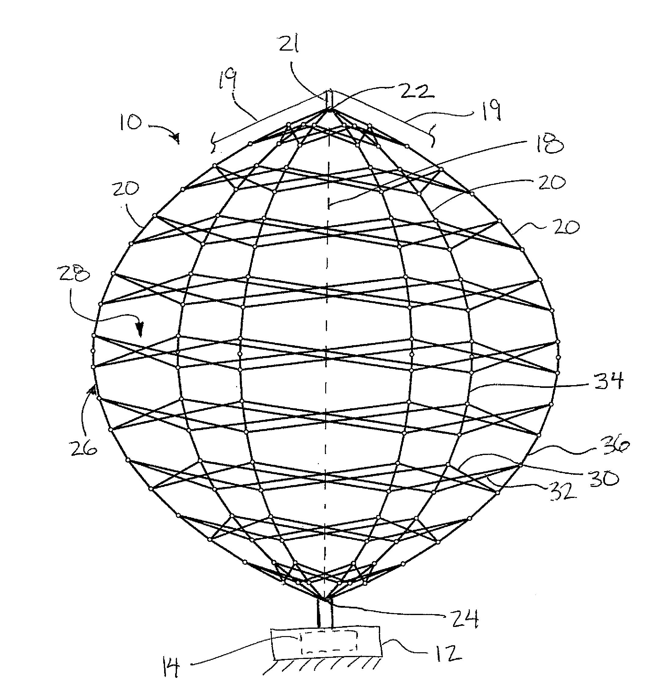
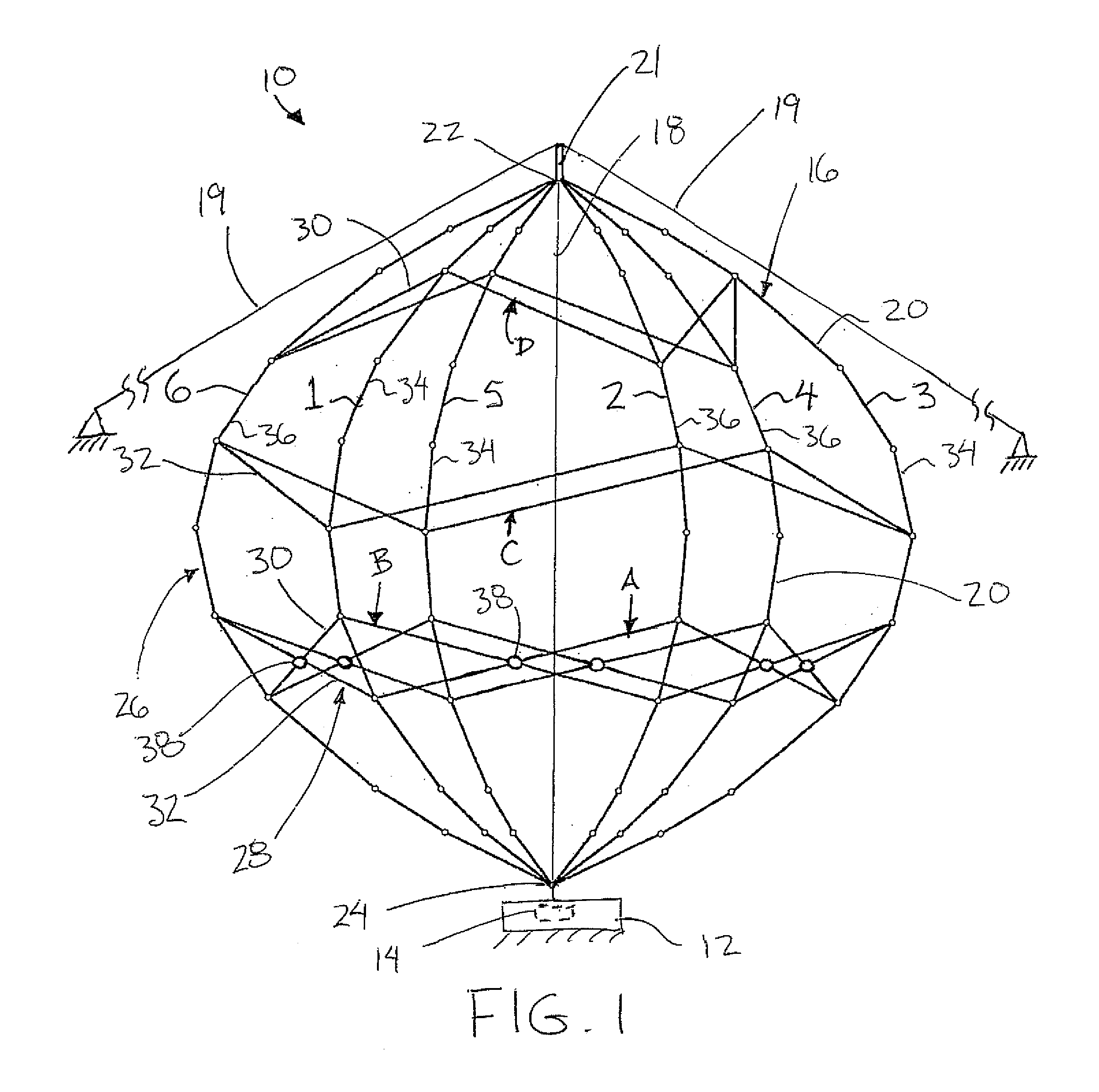
[0054]In FIG. 1, the rotor includes a vertical shaft extending along the vertical axis 18 of rotation between the top and bottom ends of the rotor. The top ends 22 of the blades in this instance are joined together with the shaft at the vertical axis of rotation at the top end of the rotor and the bottom ends 24 are similarly joined together with the shaft at the axis of rotation at the bottom end of the rotor. The shaft in this instance may be supported under tension between the top and bottom ends of the rotor to urge the blades to bow radially outwardly. This force is opposite to the compressive force applied to the blades by the circumferential support members 28 which urges the blades radially inwardly such that the blades are supported under compression in a pre-stressed condition which maintains the blades substantially rigid and fixed in orientation throughout the operation of the turbine regardless of the wind conditions.

second embodiment

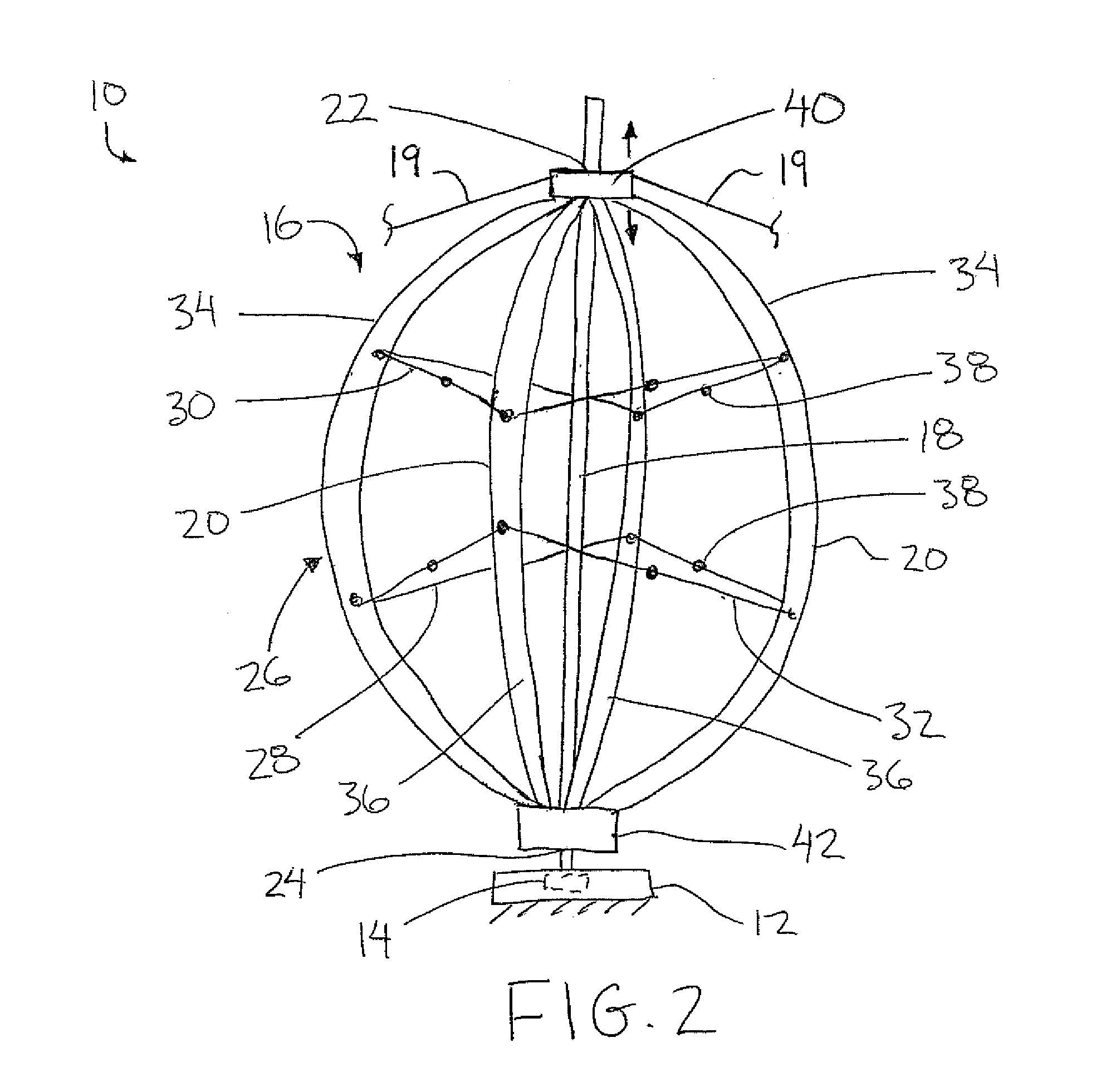
[0055]Turning now more particularly to FIG. 2, the rotor comprises a shaft similar to FIG. 1, but the top ends of the blades are shown connected with one another by a top yoke 40 supported by a suitable bearing for sliding displacement along the shaft. The guy wires 19 in this instance are connected to the top yoke 40. Similarly the bottom ends are all commonly connected on a bottom yoke 42; however the bottom yoke is fixed relative to the shaft. The top yoke 40 is supported for rotation with the shaft but remains slidable in the axial direction of the axis of rotation along the shaft relative to the bottom yoke. Alternatively, the top yoke may be fixed in the axial direction and the bottom yoke may be slidable along the shaft towards the top yoke. A suitable control mechanism in the form of a spring, hydraulic pressure or weights for example is used to pull the ends of the rotor towards one another by urging the top yoke downwardly towards the bottom yoke, or urging the bottom yoke...


PUM


Abstract

A vertical axis turbine includes a modified darrieus type rotor having at least three circumferentially spaced apart blades, each having an airfoil shape in cross section such that the blades generate a torque in a direction of rotation of the turbine about the vertical axis responsive to a generally horizontal wind across the blades. Support members, for example flexible cables, are connected under tension between adjacent ones of the blades to extend in a generally circumferential direction about the turbine at an inclination from horizontal in a criss-crossing pattern with other support members. A tensioning mechanism also urges opposing top and bottom ends of the rotor towards one another such that the blades are supported under compression in a pre-stressed condition by the support members and the tensioning mechanism to maintain the blades in a substantially rigid and fixed orientation throughout the operation of the turbine rotor.

Description

[0001]This application claims priority benefits from U.S. provisional application Ser. No. 61 / 254,889, filed Oct. 26, 2009.FIELD OF THE INVENTION[0002]The present invention relates to a modified darrieus or lift-type turbine in which the blades have a general airfoil-like shape and are supported for rotation above a vertical axis, and more particularly the present invention relates to a lift type turbine comprising generally circumferential support members between at least three lift-type blades.BACKGROUND[0003]Modern wind turbines are either horizontal axis turbines or vertical axis turbines. Horizontal axis wind turbines dominate the market world wide. They normally have a nacelle, rotor and blades that sit on top of a tower. The nacelle consists of the generator, planetary gearing and all the control systems necessary to operate the turbine. The rotor holds the blades (usually 3) in their positions while they rotate around the main shaft in the nacelle. These wind turbines work f...

Claims


Application Information

Patent Timeline
Patent Type & Authority Applications(United States)
IPC IPC(8): F03D3/06
CPCF03D3/005F05B2220/706Y02E10/74F05B2260/402F05B2240/212
Inventor LUX, GLENN RAYMOND
Owner LUX
Why Eureka
Try Eureka