Method and system for power management

a technology of power management and power management system, applied in non-electric variable control, process and machine control, instruments, etc., can solve the problems of high communication load, high and sustained load in process controllers, and important and complex problems

Active Publication Date: 2012-09-06
ABB (SCHWEIZ) AG
View PDF13 Cites 62 Cited by
  • Summary
  • Abstract
  • Description
  • Claims
  • Application Information

AI Technical Summary

Benefits of technology

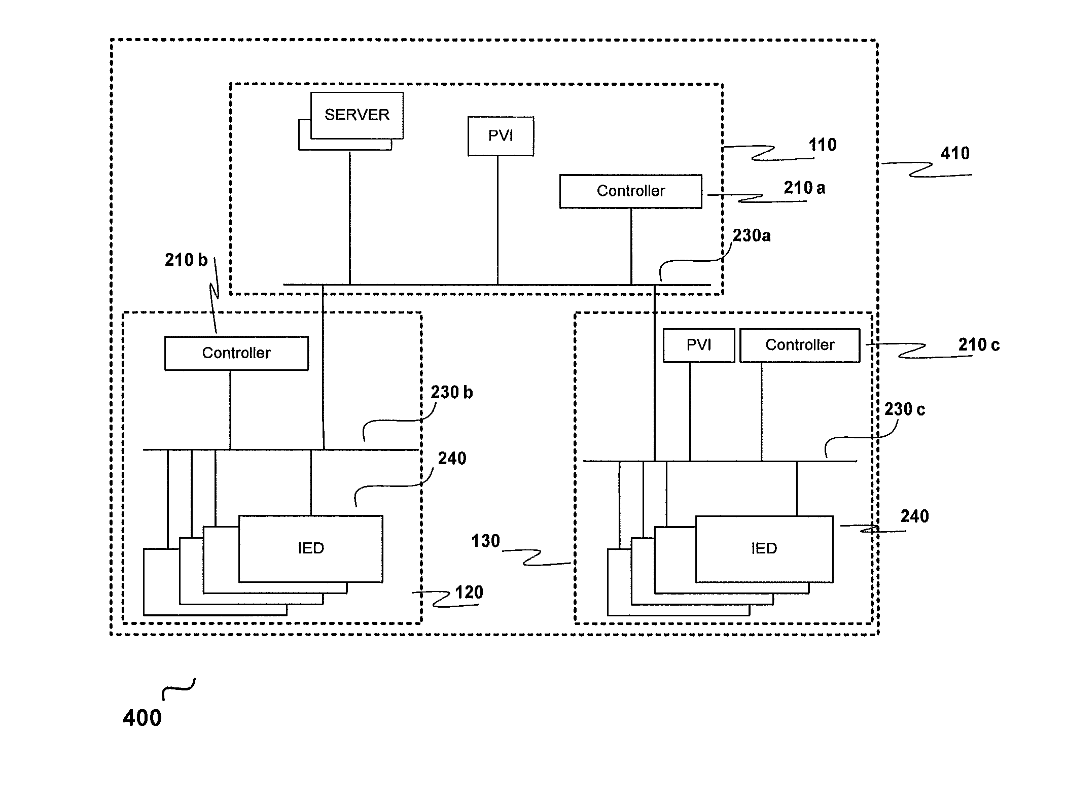
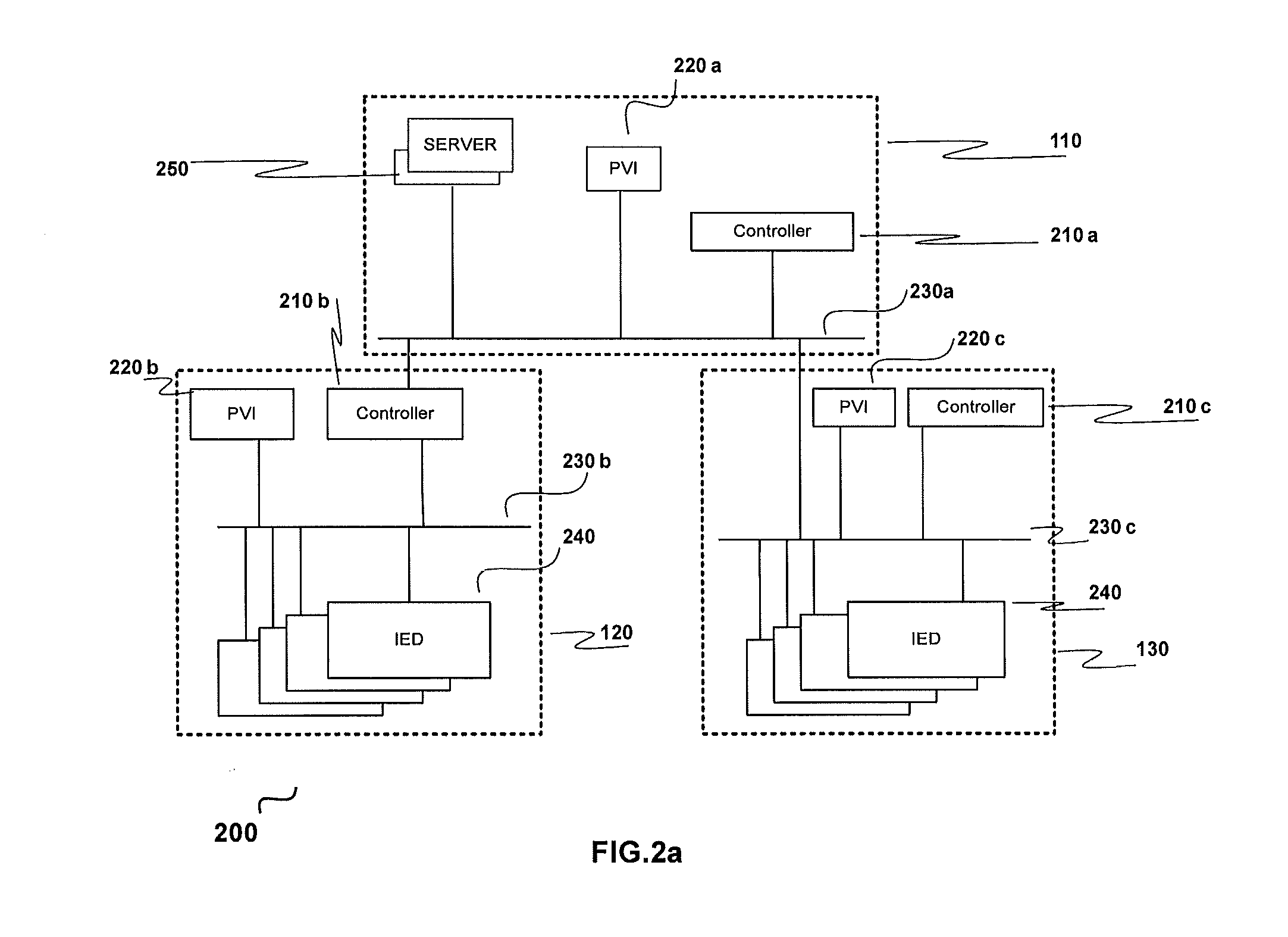
[0031]According to yet another aspect, a device (e.g., controller) for power management in a plant electrical network is provided. The controller can be adapted and configured for power management in a first local process area within the plant electrical network and capable of communicating, over a plant communication network, with a second controller or device configured for power management in the plant electrical network in a second local process area.

Problems solved by technology

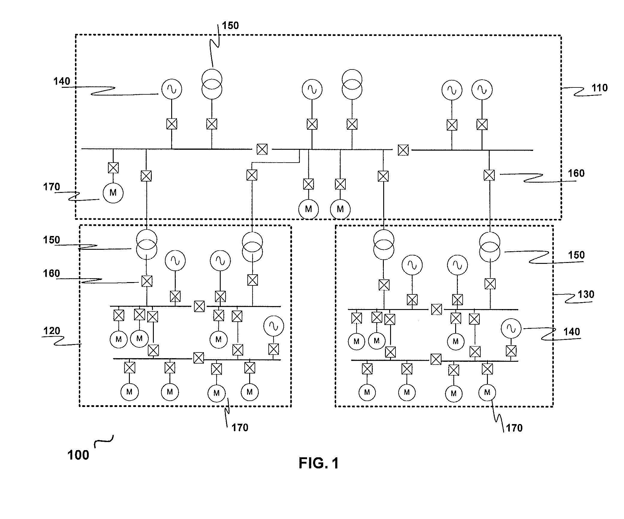
Substation automation can be an important and complex aspect to solve the power system function tasks, using state of the art technologies.
For example, centralized function implementation causes high loading due to centralization of all functions for the complete power system network, where load shedding is to be deployed.
It also results in high and sustained levels of communication loads in the process controller IED, as it would collect desired data from downstream IEDs for execution of the centralized function.
This leads to lower availability of the process controller IED for other activities.
Since the downstream IEDs are directly connected to the central process controller, it is directly exposed to the complexity of the substation configurations and connectivity.
Further, there are limitations in coverage in case of high number of islanded networks (power network that gets isolated from upstream substation due to a fault in the network) in the substation as only a particular number of islands can be handled by the centralized controller.
The undetected islands are thus left vulnerable to system disturbances, without the ‘coverage’ of the centralized load shedding function.
Also, overload situations in a downstream transformer cannot be easily detected in the centralized implementation and hence there may be no facility for downstream substation slow load shedding to lessen overloading on the transformers.
The loads can be manually shut down due to lack of any intelligent load shedding action in the downstream substation.
This results in a lack of discrete isolation of loads, thereby lessening system availability.

Method used


Image

  • Method and system for power management
  • Method and system for power management
  • Method and system for power management

Examples


example 1

CONTINGENCY EXAMPLE 1

[0087]Upstream and downstream substations are connected or LC and CCs are connected on the Plant-wide LAN on IEC61850 and a contingency occurs in the downstream substation; that is, a power source gets disconnected due to a fault:[0088](a) CC does plant wide power calculation[0089](b) CC comes up with a load shed priority until which loads have to be shed in that downstream substation and / or other downstream substations[0090](c) CC sends calculates load shed priority information over IEC61850[0091](d) LC receives the load shed priority and checks which loads priorities are less than or equal to that priority value and issues shed commands to those loads' IEDs on IEC61850.

example 2

CONTINGENCY EXAMPLE 2

[0092]Upstream and downstream substations are connected or LC and CCs are connected on the Plant-wide LAN on IEC61850 and a contingency occurs in the downstream substation; that is, a circuit breaker that is associated with the substation network changes state (open to close or close to open):[0093](a) the LC and CC check, if the circuit breaker status change results in a disintegration / change of the downstream network[0094](b) the downstream substation network segment that is still connected to the upstream substation is ‘taken care’ by the CC[0095](c) the islanded part of the substation network is ‘taken care’ by the LC, (e.g., a part of the downstream substation network is in local control mode (partial autonomous mode))[0096](d) CC does plant wide power balance calculation and the LC does the power balance calculation for the islanded network in the downstream substation[0097](e) In case there is a power deficiency in the islanded network, the LC arrives at ...

example 3

CONTINGENCY EXAMPLE 3

[0098]Upstream and downstream substations are connected or LC and CCs are connected on the Plant-wide LAN on IEC61850 and a contingency occurs in the downstream substation; that is, a circuit breaker (tie feeder) connecting the two substations trips on a fault, or LC and CCs are disconnected due to a fault in the IEC61850 communication network or Plant-wide LAN (upstream and downstream substations are still electrically connected)[0099](a) the LC takes control of the disconnected substation (from the plant network) and the downstream substation Load Shedding mode changes from remote to local mode[0100](b) CC does plant wide power balance calculation for the rest of the network except the isolated substation.[0101](c) LC does the power balance calculation for the downstream substation[0102](d) In case there is a power deficiency in the islanded network (downstream substation), the LC arrives at a load shed priority calculation and checks which loads priority are ...


PUM


Abstract

A method and a system for power management for a plant electrical network are provided. The power management system over a plant-wide communication network includes both concepts of hierarchical level and distributed level power management using multiple controllers. At least one controller in the power management system is configured for power management in a first local process area within the plant electrical network and is capable to communicate with at least a second controller configured for power management in a second local process area within the plant electrical network over the communication network.

Description

RELATED APPLICATION[0001]This application claims priority as a continuation application under 35 U.S.C. §120 to PCT / IP2010 / 000001, which was filed as an International Application on Jan. 5, 2010 designating the U.S., and which claims priority to Indian Application 2152 / CHE / 2009 filed in India on Sep. 7, 2009. The entire contents of these applications are hereby incorporated by reference in their entireties.FIELD[0002]The present disclosure relates generally to the field of power management systems, and more specifically to power management in process industries.BACKGROUND INFORMATION[0003]An electrical or power substation involves electricity transmission and distribution systems where voltage is transformed from high to low or the reverse using transformers. Electric power may flow through several substations between generating plant and consumer or load, and the voltage may be transformed in several steps.[0004]Industrial setups involve intense energy consumption and include one o...

Claims


Application Information

Patent Timeline
Patent Type & Authority Applications(United States)
IPC IPC(8): G06F1/26
CPCH02J13/0079H02J3/14H02J13/00028H02J13/00034Y04S20/222Y02B70/3225H02J2310/60
Inventor KULATHU, GANESHGUPTA, ARINJAIPAPAEVANGELOU, DIOGENISOTTO VAN DER WAL, WILLEMWIMMER, WOLFGANGNYKVIST, MARTIN
Owner ABB (SCHWEIZ) AG
Why Eureka
Try Eureka