
Industrial truck with an electric travel drive

a technology of electric travel drive and industrial truck, which is applied in the field of industrial truck electric travel drive, can solve the problems of excessive brake of a vehicle without a load, insufficient output of the travel drive in generator operation, and inability to achieve the required stopping distance, so as to prevent the occurrence of overvoltage, reduce the braking torque of the regeneratively operated travel drive, and increase the braking torque of the eddy current brake

Active Publication Date: 2012-09-06
JUNGHEINRICH AG
View PDF3 Cites 5 Cited by
  • Summary
  • Abstract
  • Description
  • Claims
  • Application Information

AI Technical Summary

Benefits of technology

[0018]The industrial truck according to the invention is equipped with an electric travel drive and controls that can switch the electric travel drive to regenerative operation to brake the industrial truck. The regenerative current thereby obtained is preferably used to recharge the vehicle battery. The industrial truck according to the invention is also equipped with an eddy current brake that is controlled or regulated by the controls to brake the industrial truck during regenerative operation of the travel drive. According to the invention, the industrial truck is additionally braked by an eddy current brake during regenerative operation of the travel drive in the industrial truck, and the braking torque generated thereby is controlled or regulated by the controls. The advantage of the additionally used eddy current brake is that the electric travel drive can also be designed according to the requirements of the travel drive of the industrial truck. The eddy current brake is also used during regenerative braking to prevent potentially occurring excessive regenerative current and hence a battery overvoltage or, under large loads, to generate additional braking torque for the industrial truck.
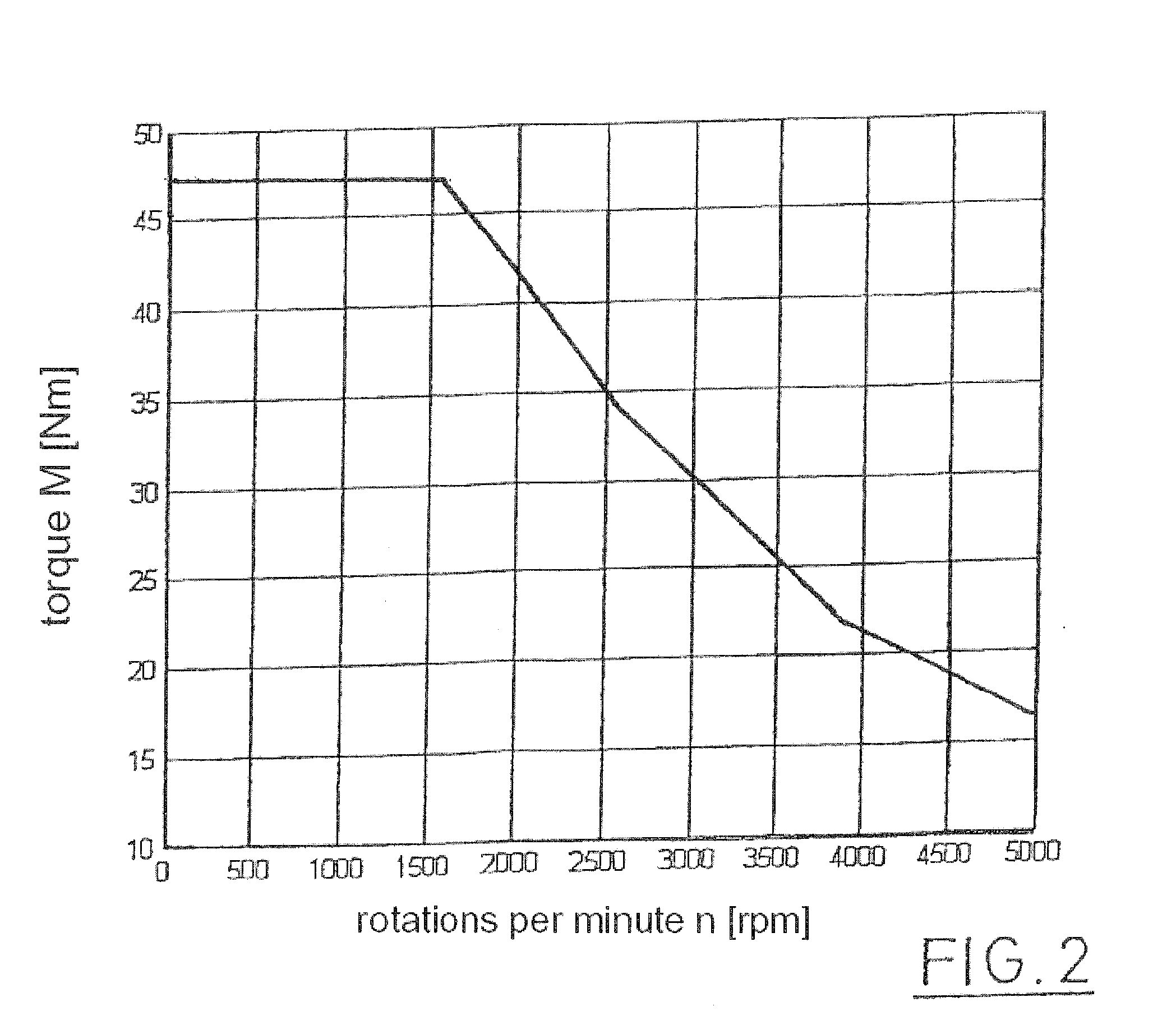
[0019]According to the invention, the controls control or regulate the eddy current brake depending on the rpms of the electric travel drive. This is based on the awareness that only a small braking torque arises with an electric travel drive, especially at high rpms in regenerative operation. This low braking torque at high rpms is supplemented by the braking torque generated by the eddy current brake, wherein the eddy-current brake generates additional braking torque. The invention therefore makes it possible to achieve sufficiently strong braking torque by additionally controlling the eddy current brake even at high rpms at which the regenerative operation only offers a slight braking torque.
[0023]In a preferred embodiment of the invention, the eddy current brake can also be alternately or additionally controlled or regulated depending on a detected battery voltage. The controls are designed to this end to detect the battery voltage arising during the generative operation of the travel drive and compare it with a predetermined maximum value. In a case in which the maximum value of the battery voltage is exceeded, the braking torque of the regeneratively operated travel drive can be reduced, and the braking torque in the eddy current brake can be increased. This embodiment can prevent the occurrence of overvoltages due to excessive regenerative current that triggers an emergency stop in the industrial truck.
[0024]Alternately, a value can be detected for the regenerative current depending on the charge of the vehicle battery, compared with a maximum value for the regenerative current, and it can be reduced when the maximum value of peak torque of the travel drive is exceeded while simultaneously increasing the braking torque of the eddy current brake. This ensures even braking with a correspondingly high braking torque of the eddy current brake independent of the battery charge.

Problems solved by technology

To brake industrial trucks, it is often unsuitable to use a single stage friction brake since, being designed for a maximum load, it excessively brakes a vehicle without a load.
Consequently, however, in particular at high speeds and high payloads, the output of the travel drive in generator operation is frequently insufficient to achieve the required stopping distances.

Method used


Image

  • Industrial truck with an electric travel drive
  • Industrial truck with an electric travel drive
  • Industrial truck with an electric travel drive

Examples


Embodiment Construction

[0033]While this invention may be embodied in many different forms, there are described in detail herein a specific preferred embodiment of the invention. This description is an exemplification of the principles of the invention and is not intended to limit the invention to the particular embodiment illustrated.

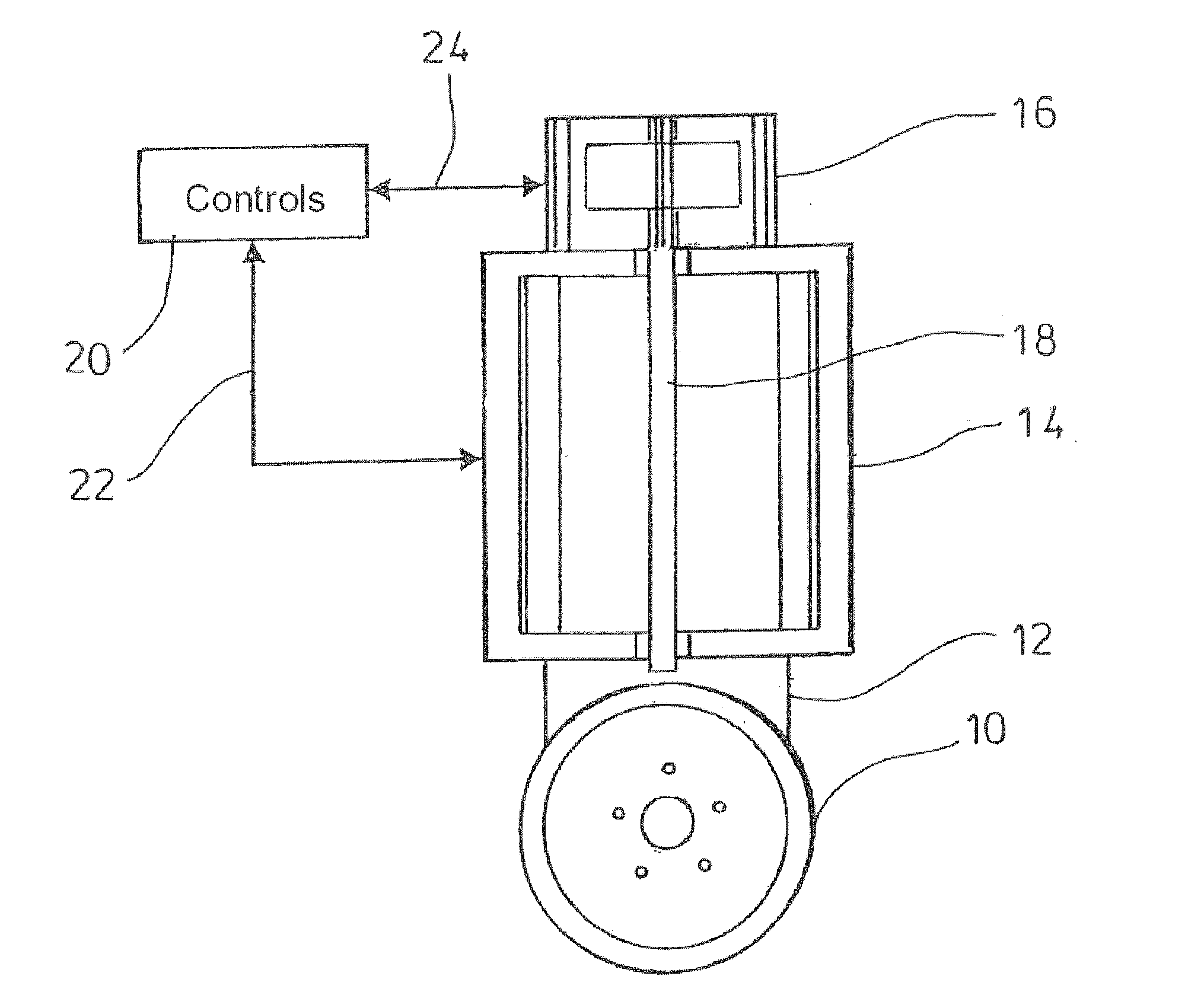
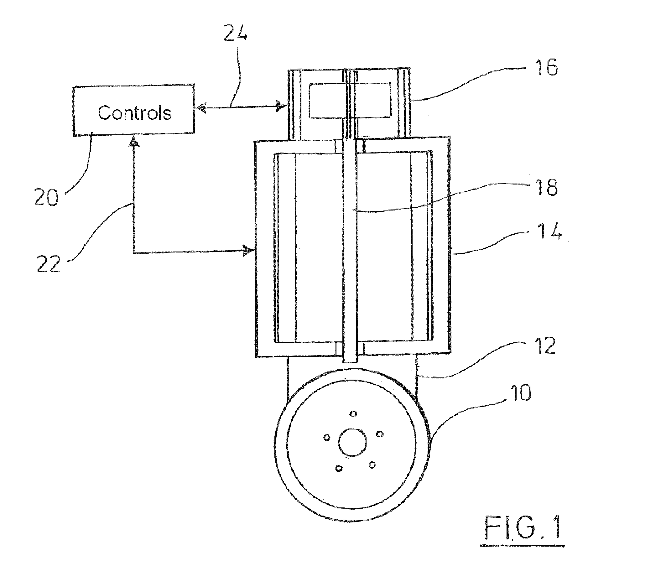
[0034]FIG. 1 schematically portrays the design of a travel drive in an industrial truck. A drive wheel 10 is driven by a single or multi-speed transmission 12 with the aid of the electric traction motor 14. The electric traction motor is for example an AC asynchronous motor, but other electrical machines can also be used such as synchronous motors. At the end of the traction motor facing away from the drive wheel, a system brake is provided that has an eddy current brake and an additional parking brake. The system brake 16 acts directly on the armature 18 of the traction motor 14. Controls 20 are provided that detect a motor rpm and motor current via a connection 22. The curr...


PUM


Abstract

Industrial truck with an electric travel drive and controls that can switch the electric travel drive to regenerative operation to brake the industrial truck, wherein an eddy current brake is provided that can be controlled or regulated by the controls during regenerative operation to brake the industrial truck, wherein the controls control or regulate the eddy current brake depending on the rpm of the electric travel drive, and wherein the controls control or regulate the eddy current brake in a manner such that the braking torque of the travel drive is supplemented at high rpms by the braking torque generated by the eddy current brake.

Description

CROSS-REFERENCE TO RELATED APPLICATIONS[0001]Not applicableSTATEMENT REGARDING FEDERALLY SPONSORED RESEARCH[0002]Not applicableBACKGROUND OF THE INVENTION[0003]The present invention relates to an industrial truck having an electric travel drive that can be switched by controls to regenerative operation in order to brake the industrial truck. In regenerative operation, the travel drive is used as a generator, the generated current of which is supplied to a battery.[0004]An automated spring-operated brake for an industrial truck is known from EP 2 006 563 A1, the entire contents of which is incorporated herein by reference. A magnet arrangement in the form of an eddy current brake that interacts with a brake provided with friction linings can be provided in the known industrial truck.[0005]An industrial truck is known from DE 10 2006 051 264 A1, the entire contents of which is incorporated herein by reference, with a drive axle that is equipped with an electrical or hydraulic traction...

Claims


Application Information

Patent Timeline
IPC IPC(8): B60L7/18B66F9/075B60L7/28
CPCB60K7/0007B60K2007/0084B60L7/18B60L7/28Y02T10/642B60Y2200/15B66F9/07572B66F9/24H02P15/00B60L2200/44Y02T10/64Y02P90/60
Inventor HARNISCH, CARSTENPLACHTA, DOMINIKGEILSDORF, HENDRIK
Owner JUNGHEINRICH AG
Learn More