Respiratory system connector

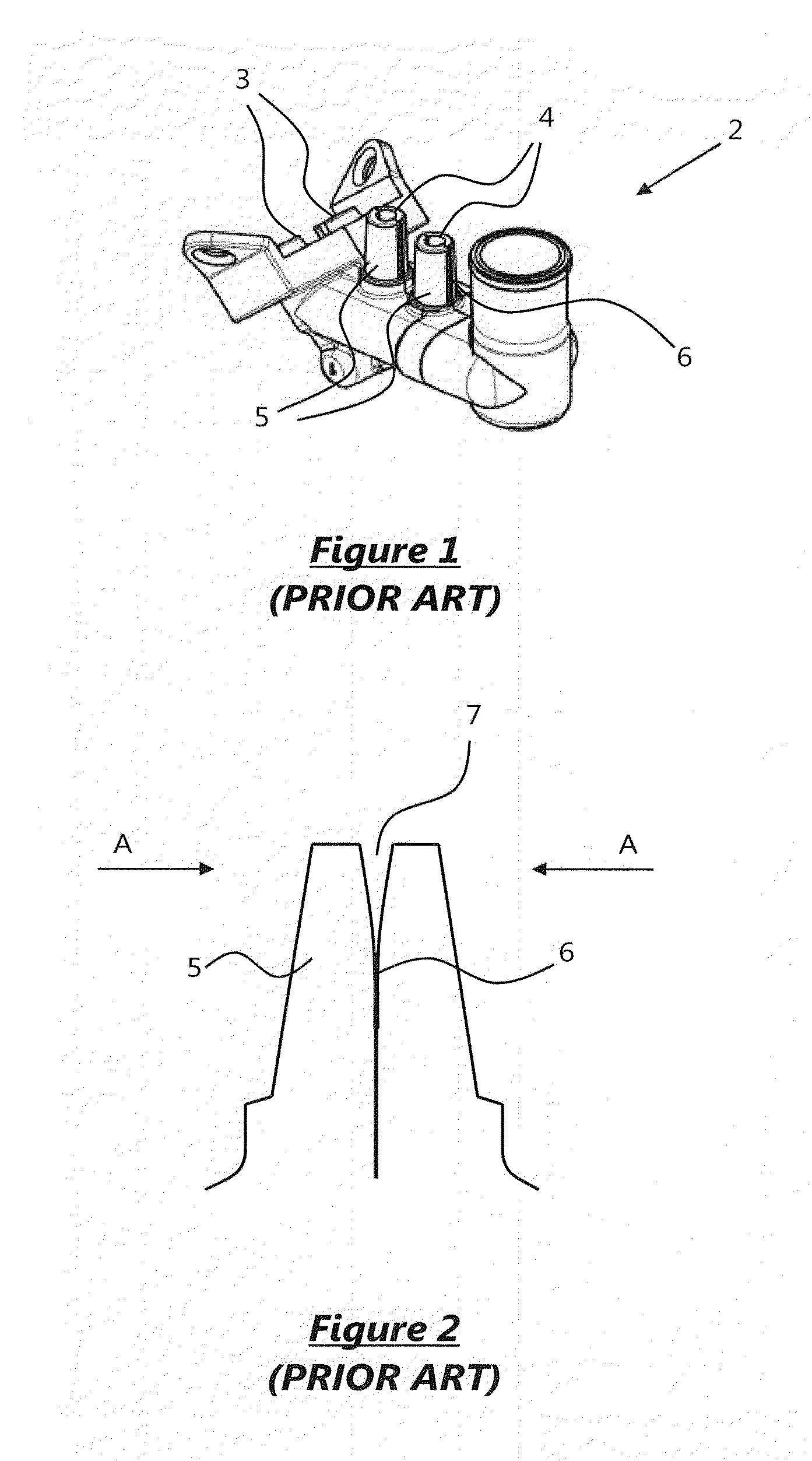
a technology for respiratory systems and connectors, applied in respiratory apparatus, other medical devices, respirators, etc., can solve the problems of individual components warping in the vicinity of the spigot formation b>5, and the connector in use is possible to fail, so as to improve the structural rigidity

Inactive Publication Date: 2012-09-13
INTERSURGICAL AG
View PDF8 Cites 16 Cited by
  • Summary
  • Abstract
  • Description
  • Claims
  • Application Information

AI Technical Summary

Benefits of technology

[0018]The first and further spigots may be located adjacent one another in a common surface of the connector body. The first and further spigots may share a common adjoining wall p

Problems solved by technology

However the manufacture of the individual component parts by injection moulding has been found to cause a likelihood that the individual components can become warped in the v

Method used


Image

  • Respiratory system connector
  • Respiratory system connector
  • Respiratory system connector

Examples


Embodiment Construction

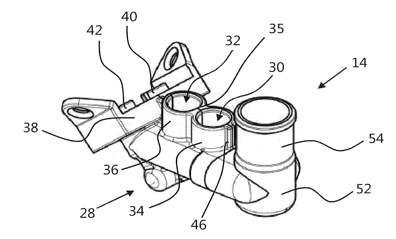
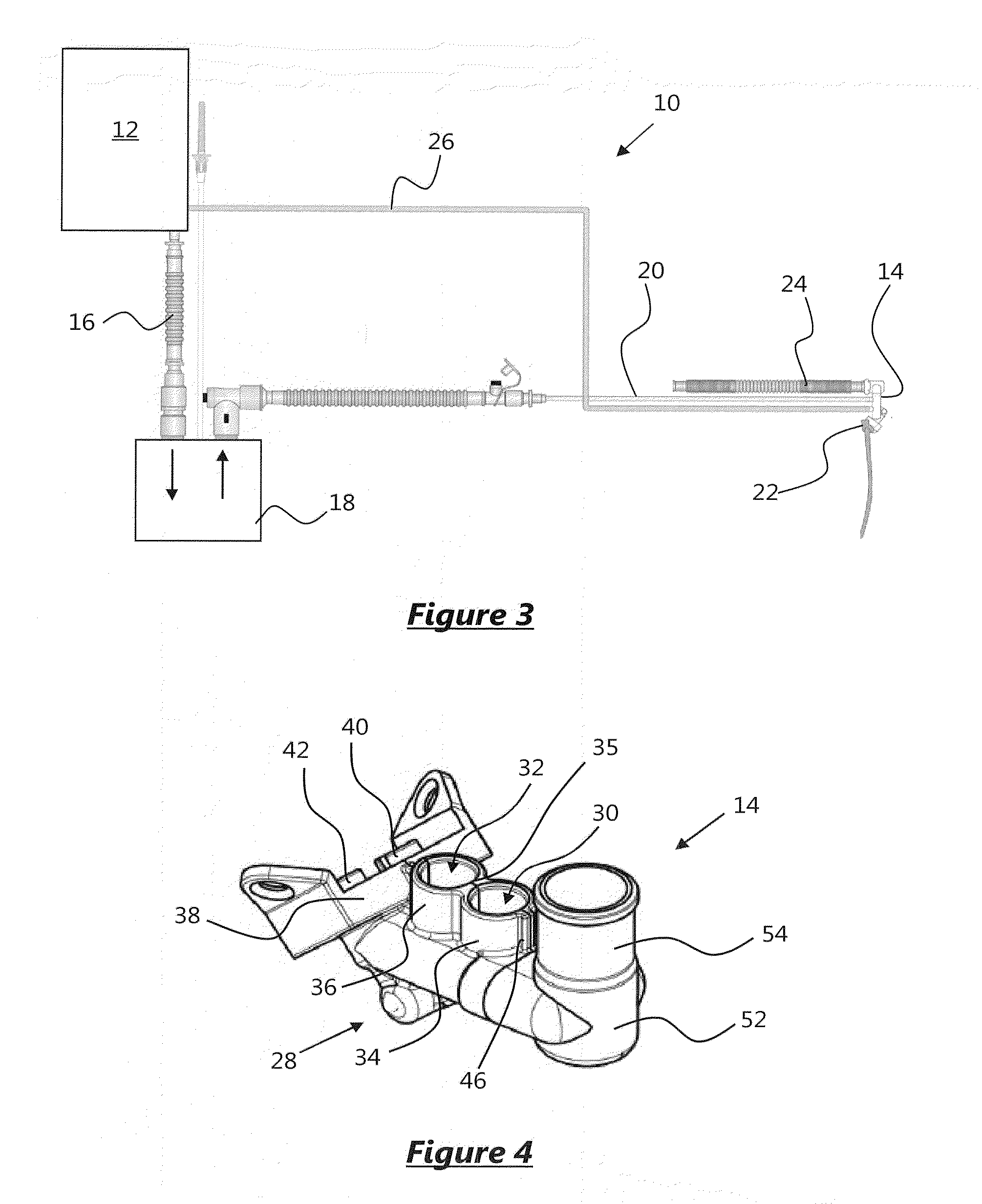
[0042]Turning firstly to FIG. 3, there is shown a respiratory system in which a connector according to the present invention may be used. The system 10 may be referred to in the art as a continuous positive airway pressure (CPAP) system and comprises a flow driver 12 for pressurising airflow to the connector 14. The pressure provided by the flow driver 12 may be substantially constant in use. Flow from the flow driver 12 passes along conduit 16 to a humidifier 18 prior to passing to the connector 14 via conduit 20.

[0043]The flow passes through the connector 14 to a patient interface connection 22 for inhalation by a patient. Exhaled air returns through the connector 14 and passes through exhaust tube 24. The pressure at the patient interface connection 22 is also monitored by connection of conduit 26 to the patient interface via connector.

[0044]The particular system of FIG. 3 allows for a CPAP delivery system for infants and accordingly the connector 14 provides for the splitting of...


PUM


Abstract

The invention concerns a respiratory ventilation connector for connection in the flow path between a patient interface and one or more fluid conduits in a respiratory ventilation system. The connector has first and second opposing body portions joined together so as to define a connector body having a first port, a second port and an internal passageway for fluid communication between said first and second ports. Each body portion has respective first and second spigot portions arranged in use to form an upstanding circumferential spigot formation about the first port. The spigot formation has an internal diameter which is greater than the diameter of the port so as to allow reception of a tubular fluid conduit within the spigot for communication with the first port in use.

Description

[0001]This application claims the priority benefit of UK Application Serial No. 1104163.9, filed Mar. 11, 2011, which is hereby incorporated by reference in its entirety.FIELD OF THE INVENTION[0002]The present invention relates to a connector for a respiratory system and, more particularly, although not exclusively, to a connector for connection in the flow path between a patient interface and a flow driver.BACKGROUND OF THE INVENTION[0003]Respiratory flow or ventilation systems typically comprise one or more devices for controlling or regulating flow to a patient interface, such as a mask, and a series of ducts for providing a flow path to and from the patient interface. The nature of the devices and the flow connections formed there-between is dependent on the type or method of ventilation being undertaken.[0004]In FIG. 1, there is shown a connector 2 for a continuous positive airway pressure (CPAP) system. The connector has a first set of ports 3 for connection to a patient mask ...

Claims


Application Information

Patent Timeline
IPC IPC(8): A61M16/08
CPCA61M16/06A61M16/0666A61M16/0833A61M16/0875A61M16/16A61M16/0816A61M39/105
Inventor BOWSHER, RICHARD
Owner INTERSURGICAL AG
Why Eureka
Try Eureka