Choke Assembly

a choke assembly and choke technology, applied in the direction of separation process, instruments, borehole/well accessories, etc., can solve the problems of emulsifying oil and water phases, affecting the effect of choking, and affecting the choking effect of the choke assembly, so as to achieve the effect of effective choking mechanism, effective choking regime, and reduction of cross-sectional area

Active Publication Date: 2012-09-13
CAMERSON INT CORP
View PDF10 Cites 30 Cited by
  • Summary
  • Abstract
  • Description
  • Claims
  • Application Information

AI Technical Summary

Benefits of technology

[0030]The inlet may be oriented to direct fluid into the separation chamber perpendicular to the longitudinal axis of the separation chamber. However, it is preferred that the inlet is angled to direct fluid into the separation chamber at an angle to the normal to the longitudinal axis, such that the incoming fluid is directed into the separation chamber in a downstream direction. When the inlet is also arranged to direct the incoming fluid at an angle to the perpendicular to the longitudinal axis of the separation chamber, the fluid is caused to flow in a helical path in the downstream direction within the separation chamber. Most preferably, the inlet is angled such that the fluid rotating within the separation chamber is caused to avoid impacting the incoming fluid, that is pass the inlet in a downstream position with sufficient distance to prevent the incoming fluid from contacting fluid already rotating within the separation chamber. This considerably reduces impact and collisions between fluid streams and impacts of fluid with surfaces within the separation chamber, in turn reducing or minimising fluid shear.
[0138]As noted previously, the methods and apparatus of the various aspects of the present invention are particularly suitable for use in the processing of fluid streams produced from subterranean wells, in particular fluid streams produced from oil and gas wells. Accordingly, in a further aspect, the present invention provides an installation for the processing of fluid streams produced from a subterranean well comprising an assembly as hereinbefore described. The efficient separation of fluid streams produced from subterranean wells, in particular the separation of gas, water and oil phases from a produced fluid stream, is particularly important in the case of subsea wells. It is commonly the case that water produced from a well is required to be separated from co-produced oil and gas and pumped back into the subterranean formations. The choke assemblies of the present invention may be advantageously applied in the separation of water from a fluid stream produced from a subsea well, allowing the water to be returned to the underground formations without the need for the fluid stream to be produced all the way to the surface of the sea. Accordingly, the present invention also provides a subsea installation comprising a choke assembly as hereinbefore described.

Problems solved by technology

However, there are several significant drawbacks with both designs of choke, in particular the design employing an external cage.
However, conventional choke assemblies provide an obstacle to achieving the desired fluid separation.
As a result of this arrangement, the fluid passing through the choke assembly is subjected to very high rates of shear.
This in turn generates significant mixing of the fluid phases, in some cases resulting in emulsification of the oil and water phases.
This mixing significantly hinders the separation of the water, oil and gas phases.
In addition, the well may produce quantities of metal particles that enter the choke, for example as a result of equipment wear or failure upstream of the choke assembly.
In the designs of choke discussed hereinbefore, the cage assembly is particularly vulnerable to damage from solids entrained with the fluid stream.
Small particles entrained with the fluid generates a very high rate of wear on the cage and especially the plug, leading to poor control of the fluid flowrate and / or pressure and eventual failure of the choke.
In extreme, but not uncommon cases, large solid particles impacting the cage assembly can destroy the cage.
In all such cases, the inevitable result is that the choke assembly requires replacement.
In the case of a subsea installation, perhaps at a depth of many thousands of feet of water, the replacement of a choke is a difficult, dangerous and time consuming task, during which production from the well may need to be shutdown.
Chokes having the external cage / internal plug design are particularly vulnerable to damage and failure from entrained solids.
Choke assemblies located close to the wellhead are particularly vulnerable to solids produced from the well.
However, as such choke assemblies are typically operating at or close to wellhead pressure, their failure can lead to a potentially dangerous situation and their replacement is a particularly difficult task, especially at great depths of water.

Method used


Image

  • Choke Assembly
  • Choke Assembly
  • Choke Assembly

Examples


Embodiment Construction

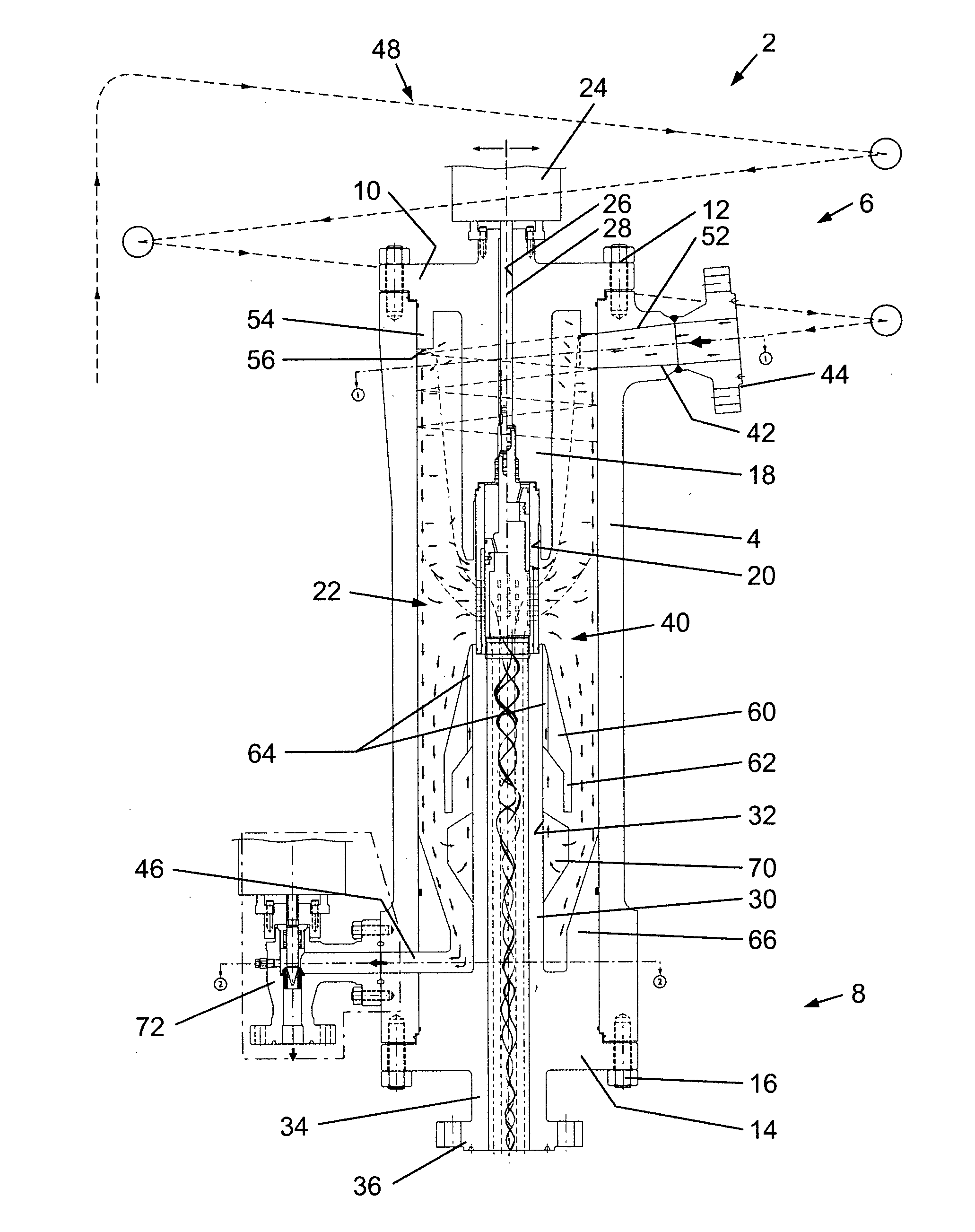
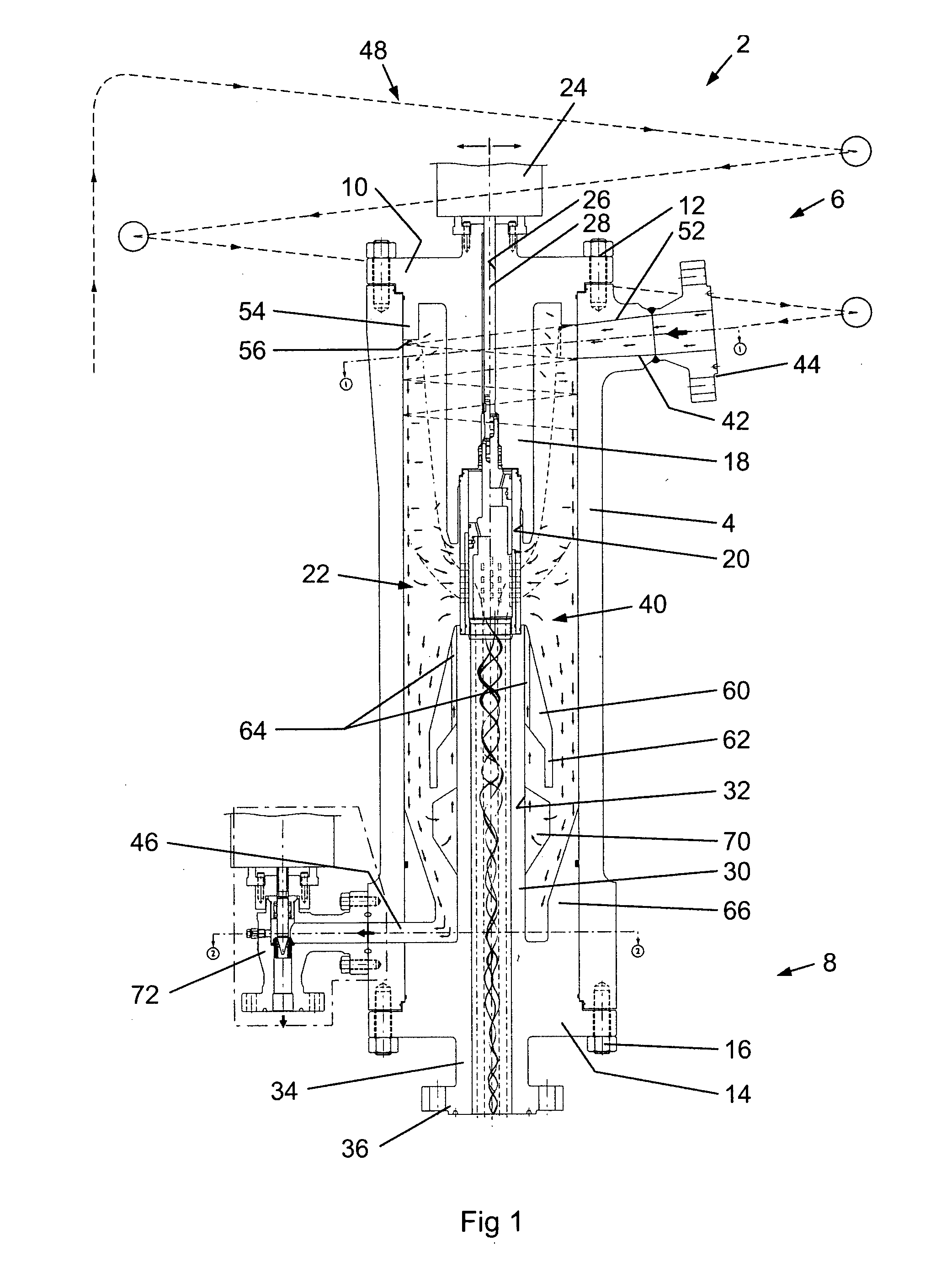
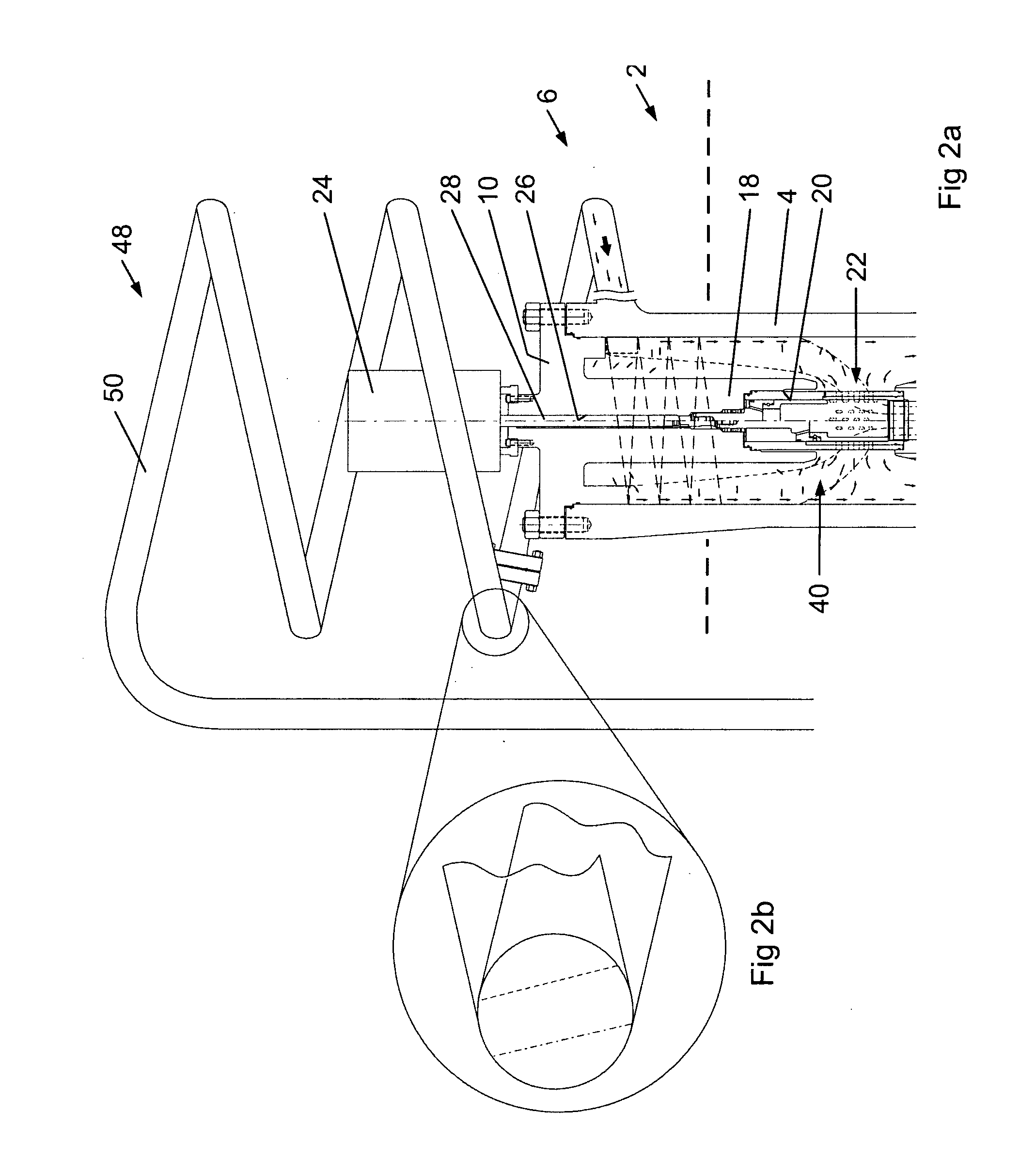
[0155]Referring to FIGS. 1 and 2a, there is shown a choke assembly, generally indicated as 2. The choke assembly comprises a generally cylindrical housing 4 having an inlet end, generally indicated as 6, and an outlet end, generally indicated as 8. A first cap 10 is mounted on the housing 4 by bolts 12 to enclose the inlet end 6. A second cap 14 is mounted on the housing 4 by bolts 16 to enclose the outlet end of the housing. The first and second caps 14, 16 are formed to provide several additional functions, as follows:

[0156]The first cap 10 has a central mandrel 18 extending therefrom coaxially within the housing 4, the distal end of the mandrel 18 being formed with a cylindrical recess 20 to provide a housing and support for the upper portion (as viewed in FIG. 1) of a choke element, generally indicated as 22. The choke element may be of any conventional design, with the arrangement shown in FIG. 1 being of a plug and cage type. The details of a preferred choke element are shown ...


PUM

PropertyMeasurementUnit
angleaaaaaaaaaa
angleaaaaaaaaaa
angleaaaaaaaaaa

Abstract

A choke assembly comprises an inlet (48) for a multiphase fluid stream, the stream comprising a first relatively heavy fluid phase and a second relatively light fluid phase; a first fluid outlet (116); a choke element (22) disposed between the inlet and the first fluid outlet operable to control the flow of fluid between the inlet and the first fluid outlet; a separation chamber (40, 114) disposed to provide separation of phases in the fluid stream upstream of the choke element; and a second outlet (118) for removing fluid from the separation cavity. The choke assembly is of particular use in the control of fluid streams produced from a subterranean well, in particular oil and gas produced from a subsea well.

Description

CROSS-REFERENCE TO RELATED APPLICATIONS[0001]Not applicable.STATEMENT REGARDING FEDERALLY SPONSORED RESEARCH OR DEVELOPMENT[0002]Not applicable.BACKGROUND[0003]The present invention relates to a choke assembly for controlling the flowrate or pressure of a fluid. The invention relates in particular to a choke assembly for use in the control of flow of oil and / or gas streams, especially in the control of fluid streams produced from subterranean wells. The choke assembly of the present invention is particularly suitable for use in subsea installations for the drilling of subterranean wells and / or the subsea production of oil and gas.[0004]The flowrate and / or pressure of a fluid stream are generally controlled in use by some form of valve assembly, in which the size of the orifice or conduit through which the fluid is caused to pass is altered. A particular form of assembly commonly employed for the control of fluid flowrate and / or pressure is a choke assembly. Known choke assemblies co...

Claims


Application Information

Patent Timeline
Patent Type & Authority Applications(United States)
IPC IPC(8): G05D7/01F15C1/16
CPCB01D17/0217E21B33/035E21B43/36E21B43/38F17D1/005E21B43/34B01D45/12B01D2221/04A61M16/00B01D21/267B01D17/047F17D3/05A61M16/0866Y10T137/2597Y10T137/0324Y10T137/3006Y10T137/0318Y10T137/3015Y10T137/2098E21B43/35
Inventor MEEK, DEREKHOPPER, HANS PAUL
Owner CAMERSON INT CORP
Why Eureka
Try Eureka