Friction stir welding method and welding jig used therefor

a technology of friction stir and welding jig, which is applied in the direction of manufacturing tools, soldering devices, auxillary welding devices, etc., can solve the problems of significant problems, reduce and reduce the cutoff area of the margin portion, so as to enhance the quality of the external appearance of the product and reliably prevent the welding failure of the member

Inactive Publication Date: 2012-09-13
SUZUKI MOTOR CORP
View PDF15 Cites 14 Cited by
  • Summary
  • Abstract
  • Description
  • Claims
  • Application Information

AI Technical Summary

Benefits of technology

[0011]Disclosed embodiments provide a method of friction stir welding and also provide a welding jig capable of reducing a cutoff area of margin portions to enhanc

Problems solved by technology

Moreover, the external appearance of the margin cutoff surface 109 is different from that of the other portion of the surface of the product 110, resulting in a decrease in the quality of external appearance of the product 110.
Part

Method used


Image

  • Friction stir welding method and welding jig used therefor
  • Friction stir welding method and welding jig used therefor
  • Friction stir welding method and welding jig used therefor

Examples


Embodiment Construction

[0039]Disclosed embodiments will be described with reference to the accompanying drawings. It is further noted that the present invention is not limited to the embodiments disclosed hereunder.

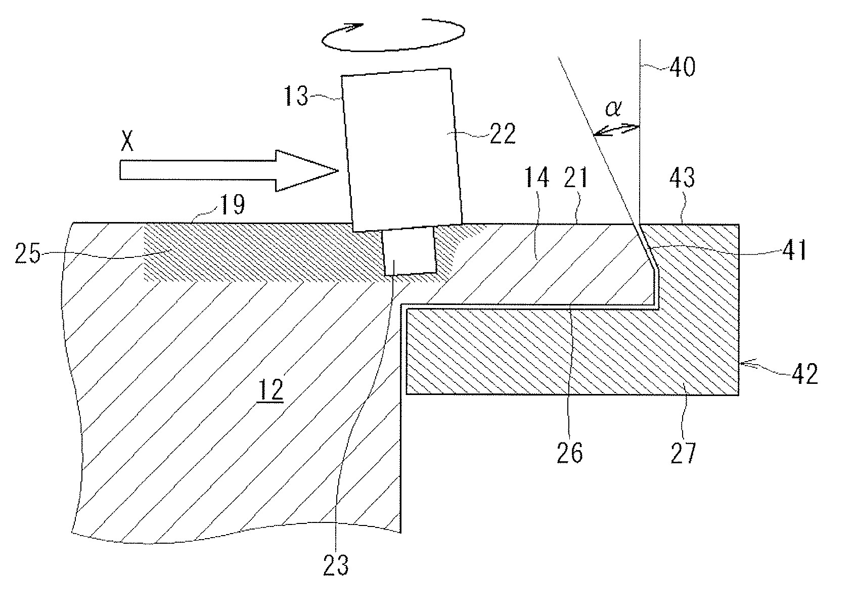
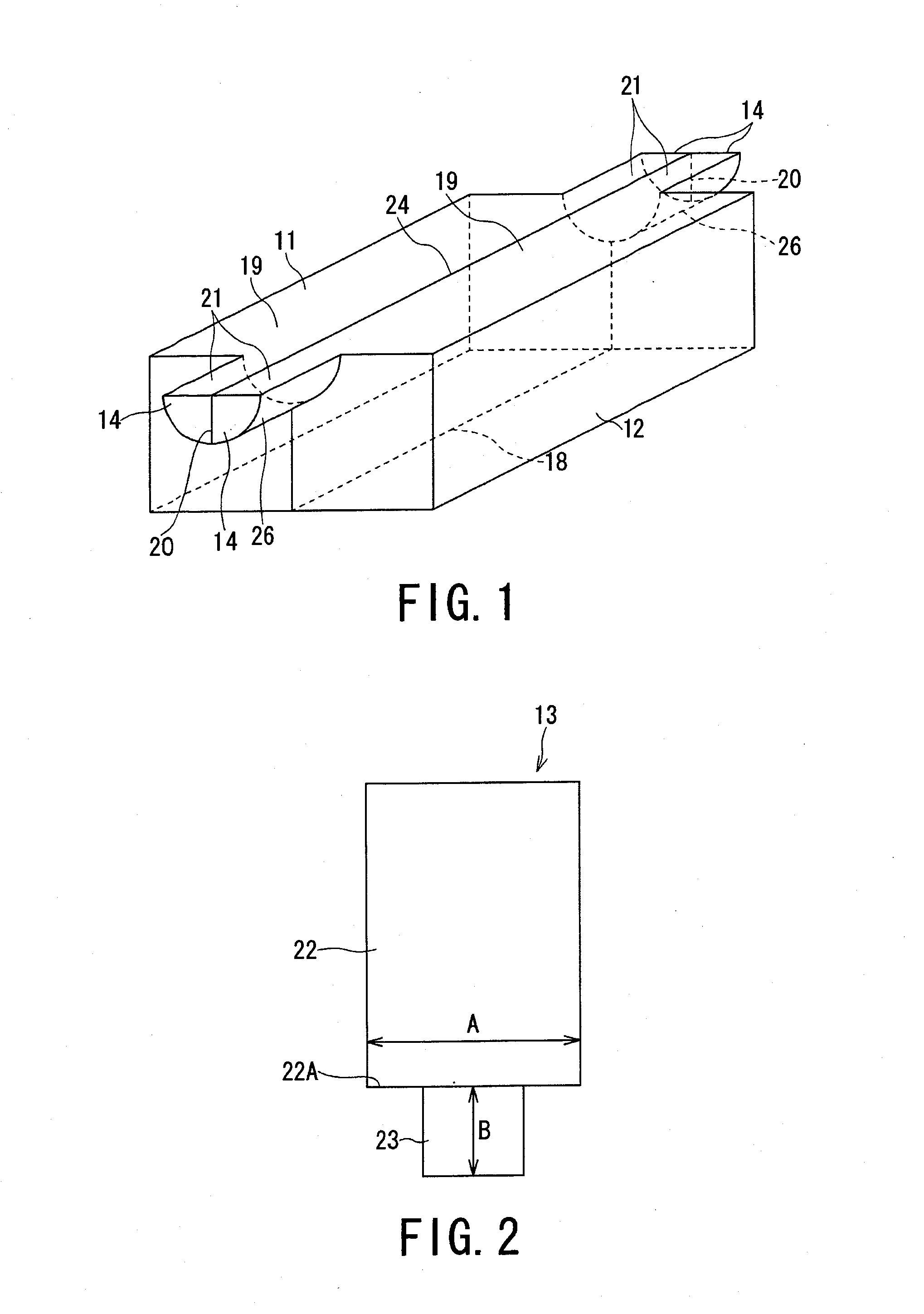
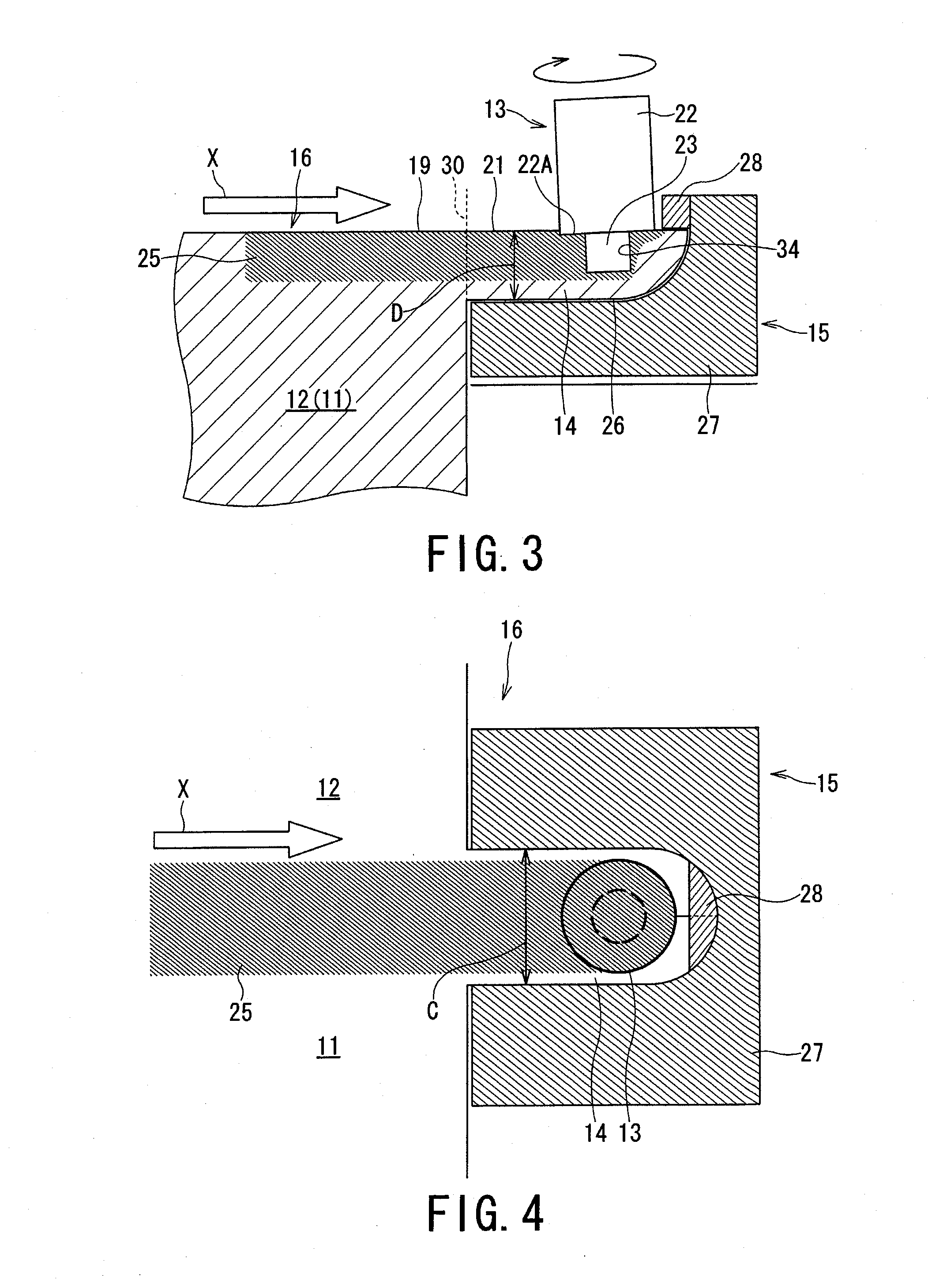
[0040]With reference to FIGS. 1 to 3, illustrating a pair of members to be welded by a friction stir welding (FSW) method, the friction stir welding is performed by using a welding tool shown in FIG. 2 in a state shown in FIG. 3.

[0041]The friction stir welding illustrated in FIG. 3 is the following method for joining. That is, a pair of members to be welded 11 and 12 (FIG. 1) are softened by frictional heat generated between the members to be welded 11 and 12 and a rotating welding tool 13 (FIG. 2) without being melted, and the members to be welded 11 and 12 are joined to each other by solid-phase welding with the utilization of a plastic flow behavior caused by the rotation of the welding tool 13 (the members to be welded 11 and 12 may be called hereinafter merely members 11 and 12).

[0042]In a...


PUM

PropertyMeasurementUnit
Lengthaaaaaaaaaa
Thicknessaaaaaaaaaa
Diameteraaaaaaaaaa

Abstract

A friction stir welding performed by preparing a pair of members to be welded, each including an abutment surface and a margin portion provided in an extended manner, the margin portion including a welding surface that is continuous to the abutment surface by using a welding tool for performing friction stir welding. The welding tool integrally includes a columnar shoulder portion and a probe portion formed on a leading end surface of the shoulder portion, the probe portion having a diameter smaller than a diameter of the shoulder portion. The abutment surfaces and the welding surfaces are brought into contact with each other so as to form a continuous welding line therebetween.

Description

PRIORITY CLAIM[0001]This patent application claims priority to Japanese Patent Application No. 2011-049000, filed 7 Mar. 2011, the disclosures of which is incorporated herein by reference in its entirety.BACKGROUND[0002]1. Field[0003]Disclosed embodiments relate to a friction stir welding method (method of performing friction stir welding) and a welding jig used for the method.[0004]2. Related Art[0005]A friction stir welding (FSW) method is a method, as shown in FIGS. 16 and 17, of welding members 101 and 102 to be welded together, and in the method, a rotating welding tool 103 is moved while being pressed against members to be welded 101 and 102 (which may be called merely “the members 101 and 102” hereinafter) are then softened by frictional heat generated between the welding tool 103 and the members 101 and 102. Then, the members to be welded 101 and 102 are joined to each other by solid-phase welding manner utilizing a plastic flow behavior caused by the rotation of the welding...

Claims


Application Information

Patent Timeline
IPC IPC(8): B29C65/06B23K20/12
CPCB23K20/124B23K20/1255B23K20/126B23K2201/18Y10T156/17B23K2203/10B23K2203/12B23K2203/14B23K2203/04B23K2101/18B23K2103/04B23K2103/10B23K2103/12B23K2103/14
Inventor YAMAUCHI, RYOKOBARI, KENTARO
Owner SUZUKI MOTOR CORP
Why Eureka
Try Eureka