Device for the flow control of a liquid or gaseous medium

a flow control and liquid or gaseous medium technology, applied in the direction of valve operation/release device, exhaust treatment, valve details, etc., can solve the problems of device damage or even destruction, as well as the electromagnet and the metering valve, and achieve the effect of not damaged or destroyed

Inactive Publication Date: 2012-09-13
ASCO NUMATICS
View PDF6 Cites 11 Cited by
  • Summary
  • Abstract
  • Description
  • Claims
  • Application Information

AI Technical Summary

Benefits of technology

[0004]The problem addressed by the invention is that of creating a device of the initially stated type, which is freeze-resistant and is not damaged or destroyed even at negative temperatures accompanied by volumetric expansion of a water-containing solution. In any case, the device should be simple and low-cost.
[0005]The problem is solved according to the invention in the case of a device of the initially stated type in that the solenoid coil is protected against deformation with respect to the valve chamber. The solenoid coil is therefore protected against deformations caused by an increase in the volume of the medium that occurs at frost temperatures. The risk of any damage occurring to the soft solenoid coil or even destruction thereof is ruled out.
[0006]It can be particularly advantageous for the solenoid coil to be sealed with respect to the valve compartment using a sealing device. Medium in the valve compartment is thereby prevented from reaching the solenoid coil.

Problems solved by technology

As a result, the device—as well as the electromagnet and the metering valve—can become damaged or even destroyed.

Method used


Image

  • Device for the flow control of a liquid or gaseous medium
  • Device for the flow control of a liquid or gaseous medium
  • Device for the flow control of a liquid or gaseous medium

Examples


Embodiment Construction

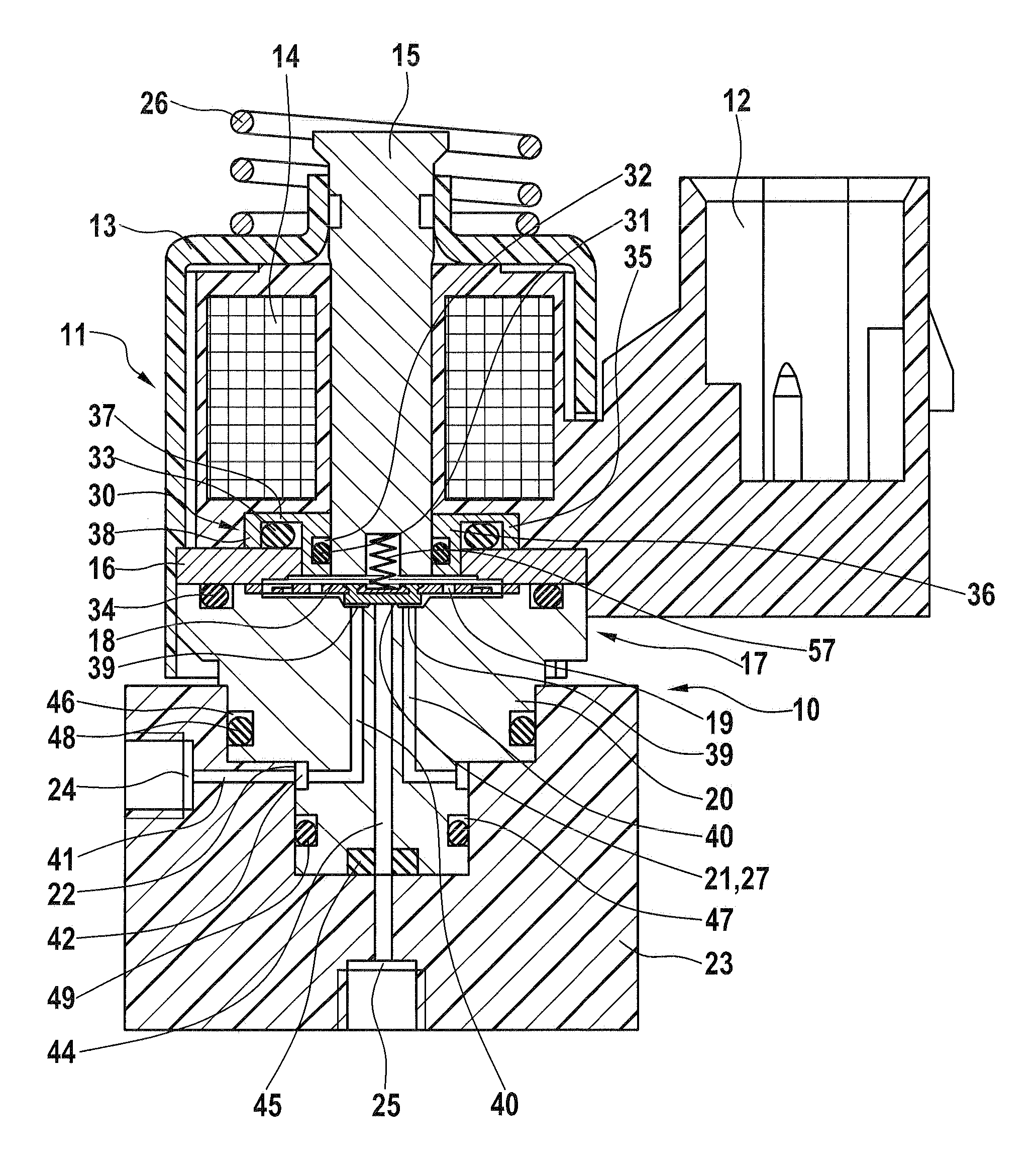
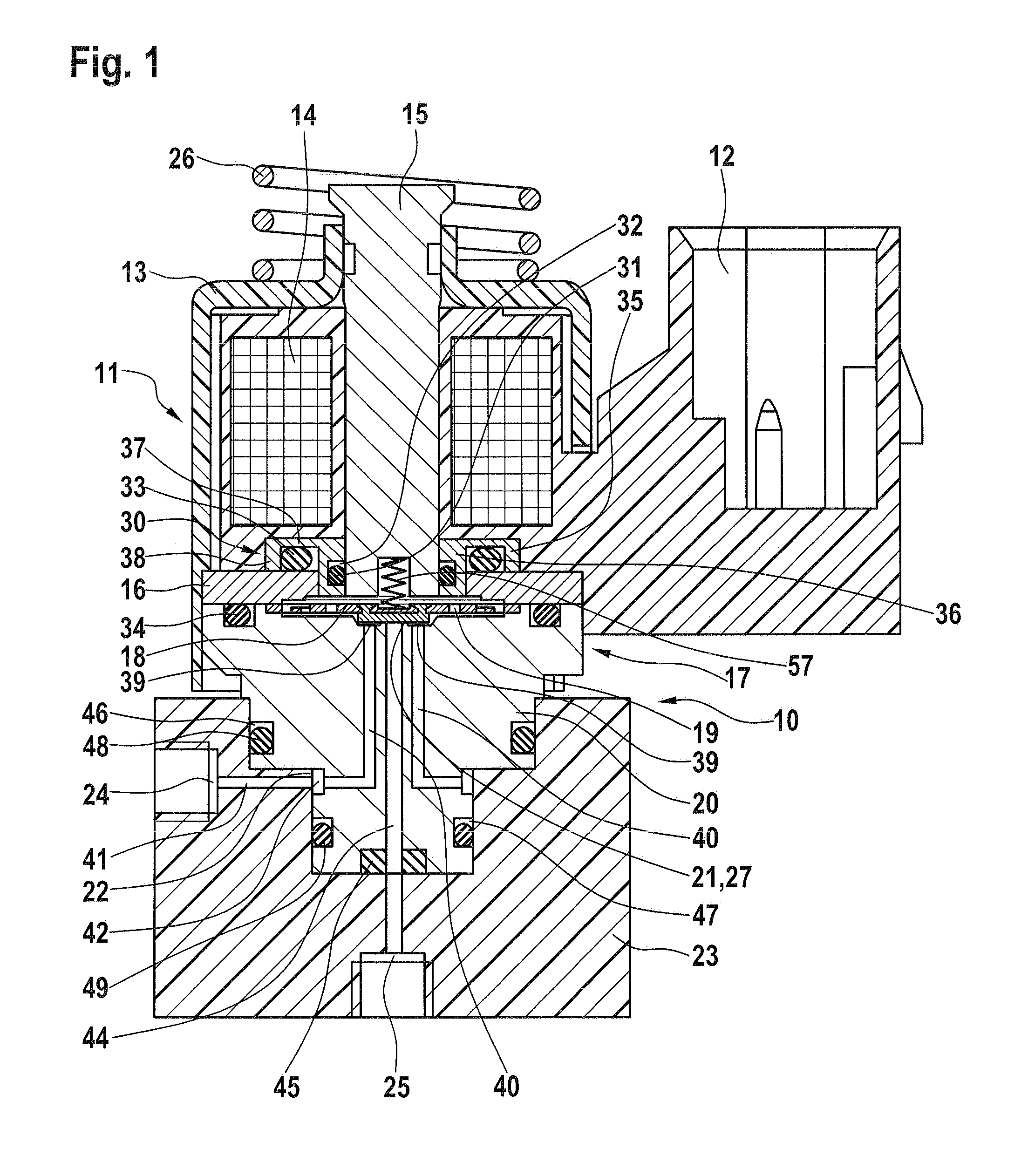
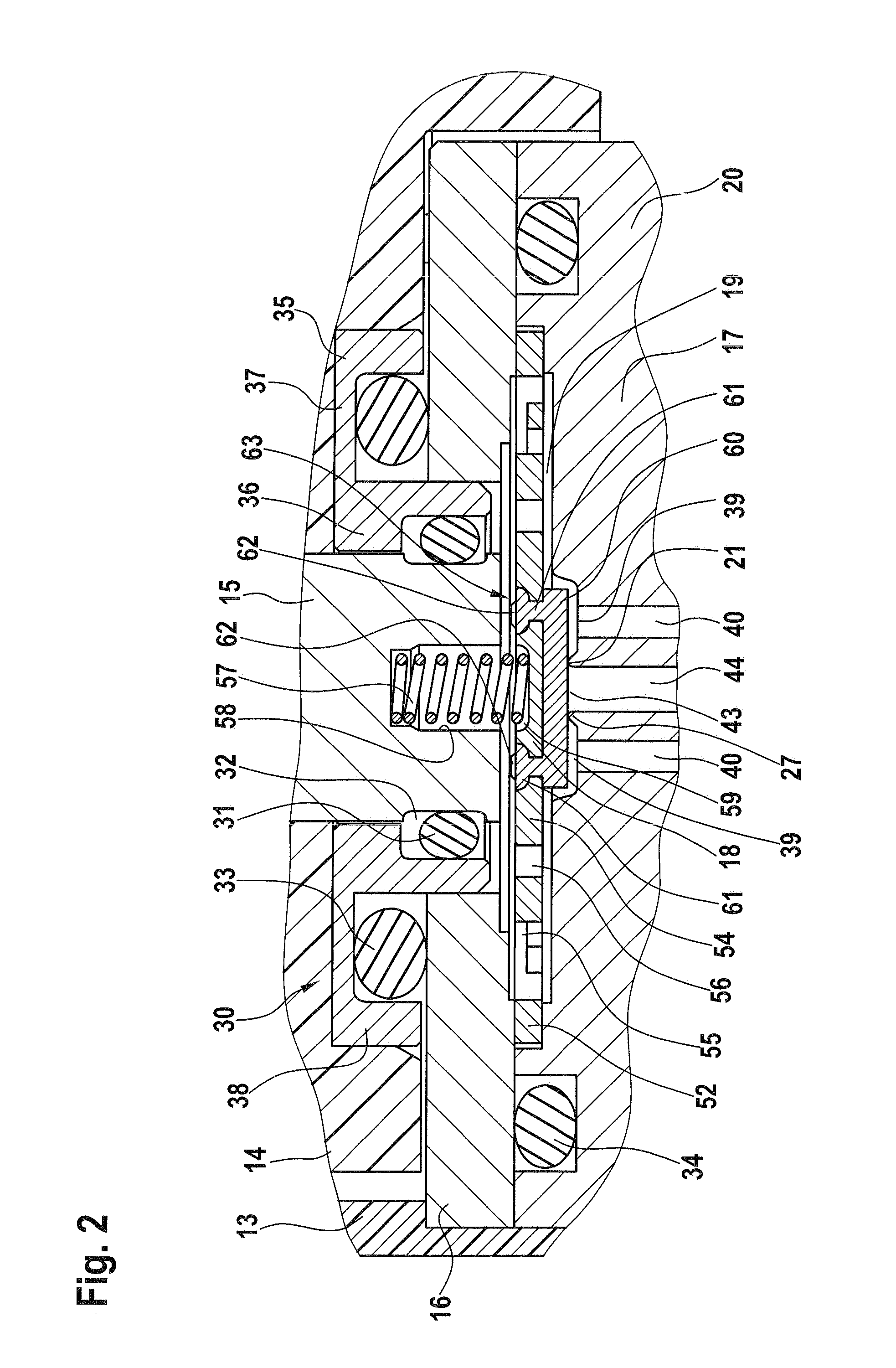
[0028]The drawings show a device 10 for the flow control of a liquid or gaseous medium, wherein device 10 is designed in particular for the metering of a fluid to be admixed into an exhaust gas treatment system. Device 10 comprises an electromagnet 11, to which an electric plug connector 12 is connected. Electromagnet 11 comprises a solenoid coil 14 with a magnetic core 15 and an end-side magnetic plate 16 in a magnet housing 13. Electromagnet 11 is designed to actuate a freeze-resistant metering valve 17 comprising a valve element 18 in a valve compartment 19 of a valve body 20 to control a valve seat 21 located there. Valve body 20 is inserted into a receptacle 22 of a housing 23 which contains a fluid inlet 24 and a fluid outlet 25. A spring 26, which is shown schematically, generates a spring force which is used to hold metering valve 17 pressed into receptacle 22 of housing 23 with a specified force by way of electromagnet

[0029]In particular when such devices 10 are used to met...


PUM


Abstract

A device for a flow control of a liquid or gaseous medium, in particular for metering a fluid to be admixed into an exhaust gas treatment system, contains an electromagnet which has a solenoid coil with a magnetic core and an end-side magnetic plate in a magnet housing, and actuates a valve element in a valve compartment of a valve body to control a valve seat located there. The solenoid coil is protected against deformation with respect to the valve compartment, and is sealed using a sealing device.

Description

CROSS-REFERENCE TO RELATED APPLICATION[0001]The invention described and claimed hereinbelow is also described in European Patent Application EP 11 002 067.4 filed on Mar. 12, 2011. This European Patent Application, whose subject matter is incorporated here by reference, provides the basis for a claim of priority of invention under 35 U.S.C. 119(a)-(d).BACKGROUND OF THE INVENTION[0002]The invention relates to a device for the flow control of a liquid or gaseous medium, in particular for metering a fluid to be admixed into an exhaust gas treatment system, comprising an electromagnet which has a solenoid coil with a magnetic core and an end-side magnetic plate in a magnet housing, and actuates a valve element in a valve compartment of a valve body to control a valve seat located there.[0003]Devices of this type are known (DE 10 2004 025 062 B4), in the case of which the valve element is composed of a long plunger in the form of a magnetic core disposed inside a solenoid coil. A meterin...

Claims


Application Information

Patent Timeline
Patent Type & Authority Applications(United States)
IPC IPC(8): F16K31/08F16K31/02
CPCF16K31/0658F01N3/2066Y02T10/24F01N2610/1453F01N2610/02Y02T10/12
Inventor AMS, FELIXWEGEHINGEL, STEFANCLEMENTE, MATTHIEU
Owner ASCO NUMATICS
Why Eureka
Try Eureka