Eureka AIR delivers breakthrough ideas for toughest innovation challenges, trusted by R&D personnel around the world.

Composites for antennas and other applications

a technology applied in the field of composites for antennas and other applications, can solve problems such as loss of efficiency and reflection of incident energy

Active Publication Date: 2012-09-13
NORTHROP GRUMMAN SYST CORP
View PDF58 Cites 28 Cited by
  • Summary
  • Abstract
  • Description
  • Claims
  • Application Information

AI Technical Summary

Benefits of technology

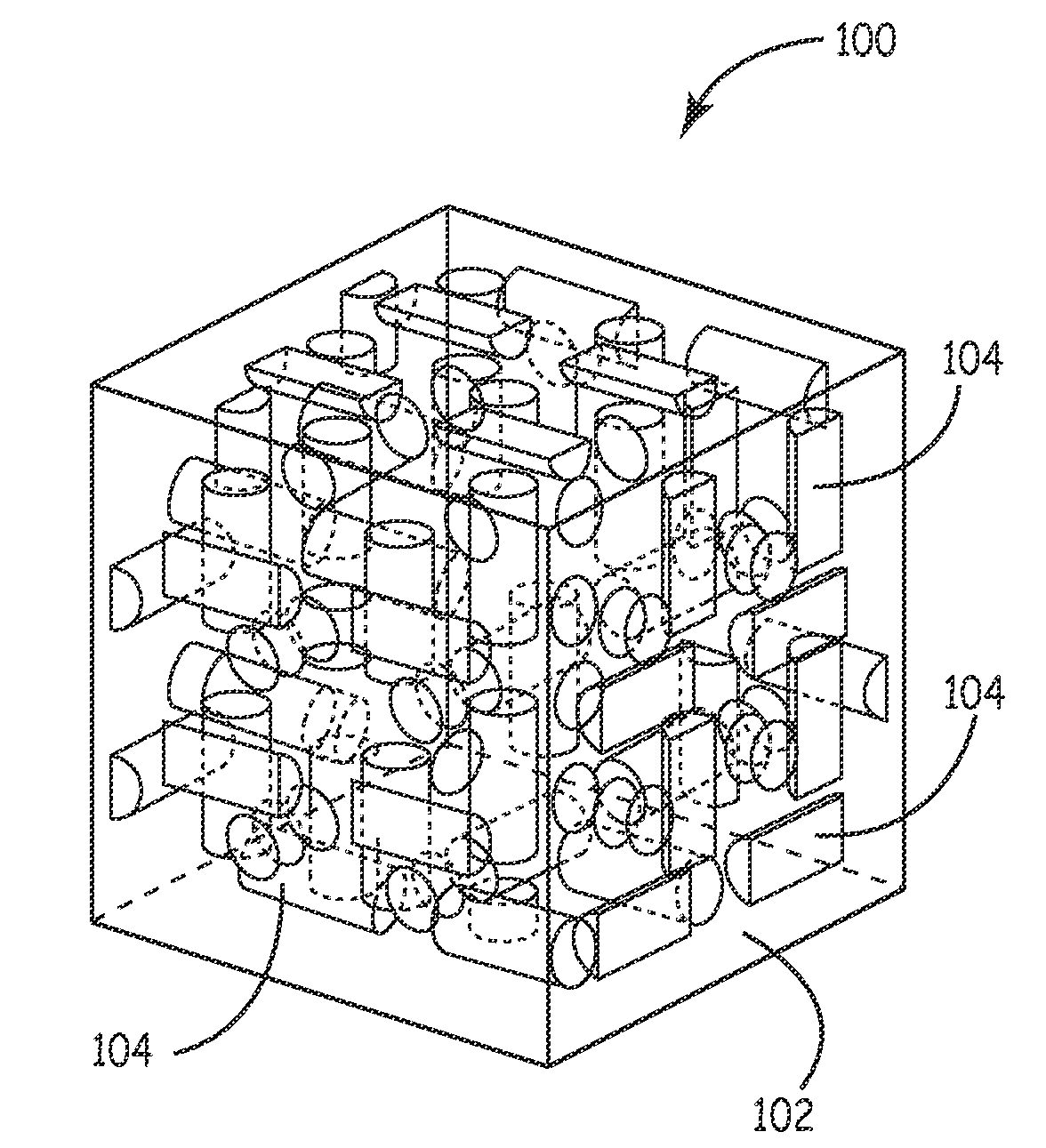
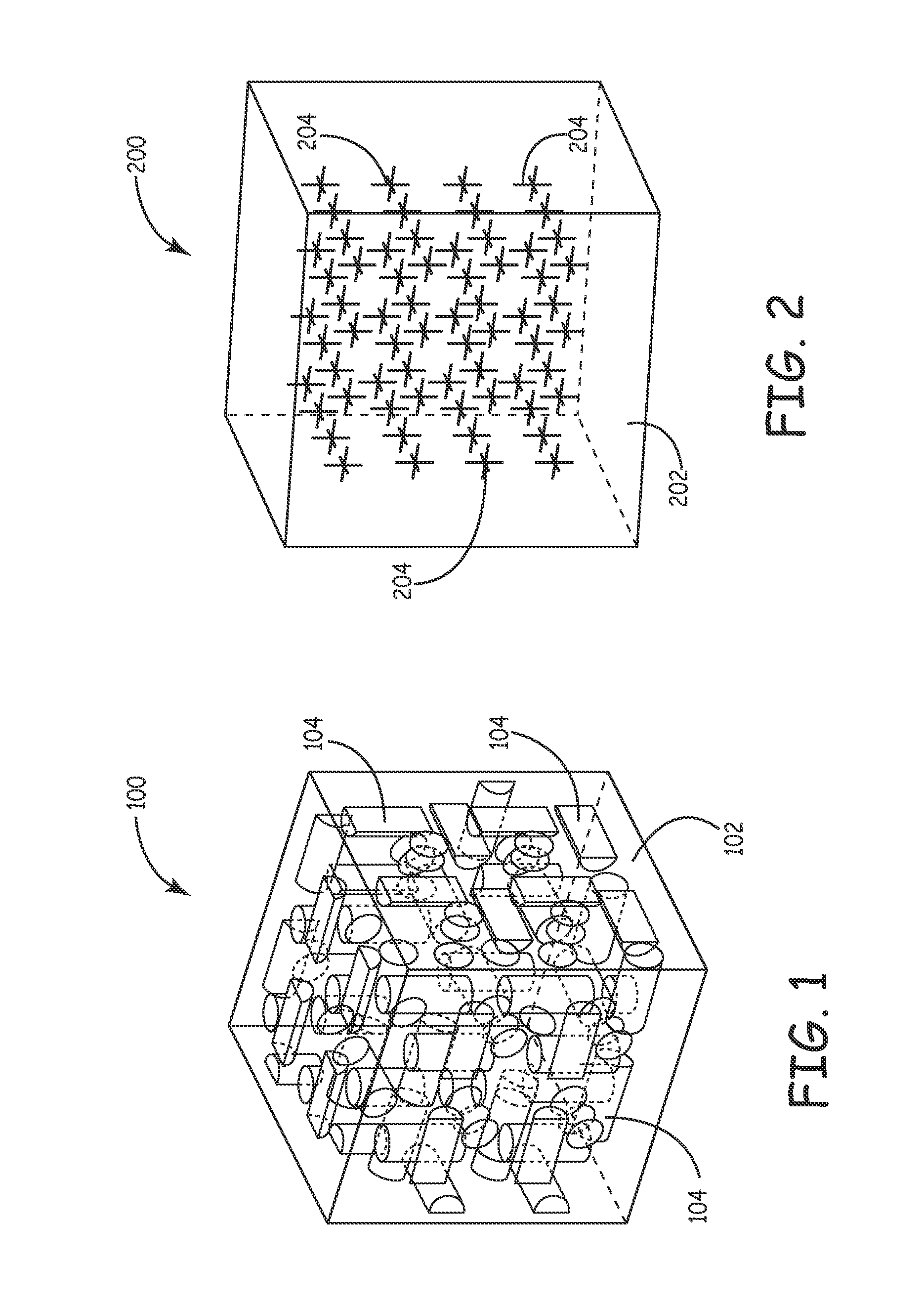
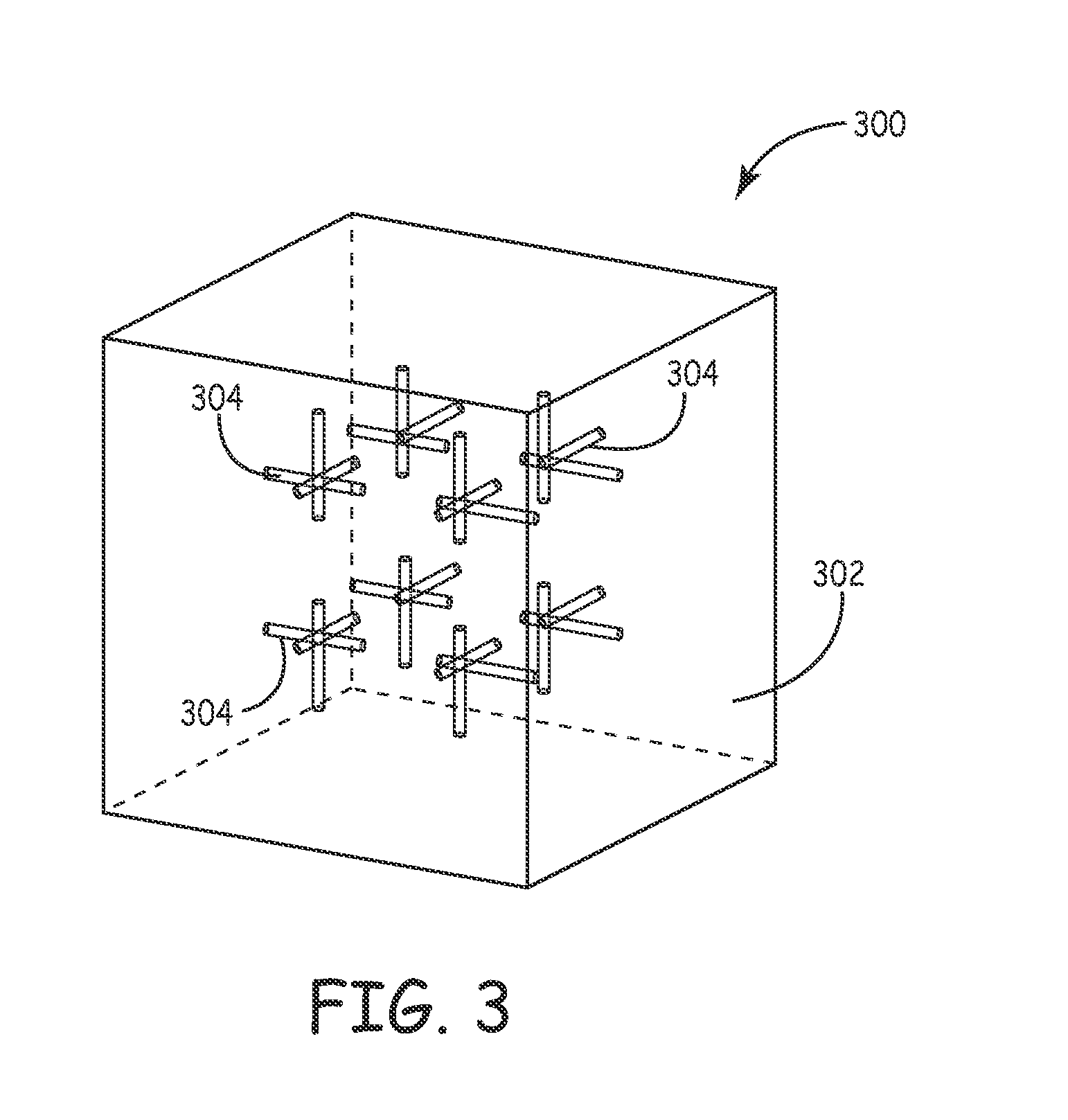
[0005]In one embodiment, composite material is provided. The composite material includes interstitial material that has at least one of a select relative permittivity property value and a select relative permeability property value. The composite material further includes inclusion material within the interstitial material. The inclusion material has at least one of a select relative permeability property value and a select relative permittivity property value. The select relative permeability and permittivity property values of the interstitial and the inclusion materials are selected so that the effective intrinsic impedance of the composite material matches the intrinsic impedance of air. Devices made from the composite include metamaterial and / or metamaterial-inspired (e.g. near-field LC-type parasitic) substrates and / or lenses, front-end protection, stealth absorbers, and mixers. Beyond the intrinsic, applications include miniature antenna and antenna arrays, directed energy weapons, EMI filters, RF and optical circuit components, among others.

Problems solved by technology

For boundaries between air and high permittivity materials, a mismatch occurs that results in a loss of efficiency.
This mismatch results in a reflection of some of the incident energy.

Method used


Image

  • Composites for antennas and other applications
  • Composites for antennas and other applications
  • Composites for antennas and other applications

Examples


Embodiment Construction

[0026]In the following detailed description, reference is made to the accompanying drawings, which form a part hereof, and in which is shown by way of illustration specific embodiments in which the inventions may be practiced. These embodiments are described in sufficient detail to enable those skilled in the art to practice the invention, and it is to be understood that other embodiments may be utilized and that logical, mechanical and electrical changes may be made without departing from the spirit and scope of the present invention. The following detailed description is, therefore, not to be taken in a limiting sense, and the scope of the present invention is defined only by the claims and equivalents thereof.

[0027]Embodiments of the present invention use metamaterials or metamaterial-inspired elements at material boundaries. The metamaterials and metamaterial-inspired elements are generally referred to as composite materials. Metamaterials are artificial materials that, in embod...


PUM

PropertyMeasurementUnit
relative permittivity propertyaaaaaaaaaa

Abstract

Composite material, devices incorporating the composite material and methods of forming the composite material are provided. The composite material includes interstitial material that has at least one of a select relative permittivity property value and a select relative permeability property value. The composite material further includes inclusion material within the interstitial material. The inclusion material has at least one of a select relative permeability property value and a select relative permittivity property value. The select relative permeability and permittivity property values of the interstitial and the inclusion materials are selected so that the effective intrinsic impedance of the interstitial and the inclusion material match the intrinsic impedance of air. Devices made from the composite include metamaterial and / or metamaterial-inspired (e.g. near-field LC-type parasitic) substrates and / or lenses, front-end protection, stealth absorbers, filters and mixers. Beyond the intrinsic, applications include miniature antenna and antenna arrays, directed energy weapons, EMI filters, RF and optical circuit components, among others.

Description

CROSS REFERENCE TO RELATED APPLICATIONS[0001]The present application claims priority to Provisional Patent Application No. 61 / 092,577 having the same title herewith filed on Aug. 28, 2008 which is incorporated in its entirety herein.BACKGROUND[0002]Electro-magnetic waves, such as radio waves, incident on a boundary between two materials reflect or pass into each material based on the difference in intrinsic impedance between the materials. For boundaries between air and high permittivity materials, a mismatch occurs that results in a loss of efficiency. This mismatch results in a reflection of some of the incident energy. One application that implements high permittivity materials is an antenna system. The use of high permittivity materials in antenna systems provides benefits. In particular, with the use of high permittivity antenna systems, the size of the antenna can be reduced compared to typical antenna systems which leads to greater applications and reduced overall sizes.[0003...

Claims


Application Information

Patent Timeline
Patent Type & Authority Applications(United States)
IPC IPC(8): G02B5/00H01Q1/00H01P7/00G01S13/00
CPCF41H13/0043F42C13/00G01S7/414G01S13/885H01Q21/00H01Q1/364H01Q21/065G02B1/007G02B5/204H01Q1/28Y10T428/31504
Inventor FULLER, CHRISTOPHER C.LAMBERG, JOHN R.GAWRONSKI, MIKE
Owner NORTHROP GRUMMAN SYST CORP
Why Eureka
Eureka Blog
Learn More