High-yield fabrication of large-format substrates with distributed, independent control elements

a technology of control elements and large-format substrates, applied in individual semiconductor device testing, semiconductor/solid-state device testing/measurement, instruments, etc., can solve the problems of unstable amorphous silicon, and affecting the performance of large-format substrates

Active Publication Date: 2012-09-13
X DISPLAY CO TECH LTD
View PDF7 Cites 163 Cited by
  • Summary
  • Abstract
  • Description
  • Claims
  • Application Information

AI Technical Summary

Problems solved by technology

The properties of such thin-film semiconductors are, however, often not sufficient for constructing a high-quality display.
Amorphous silicon, for example, may be unstable in that its threshold voltage (Vth) and carrier mobility may shift over extended periods of use.
Since OLED devices operate by current injection, variability in the TFTs can result in variability of the luminance of the OLED pixels and degrade the visual quality of the display.
Compensation schemes, such as adding additional TFT circuitry in each pixel, have been proposed to compensate for TFT variability; however, such compensation may add complexity, which can negatively impact yield, cost, and / or reduce the OLED emission area.
Furthermore, as thin-film transistor fabrication processes are applied to larger substrates, such as are often used for large flat-panel television applications, the variability and process cost may increase.
For example, semiconductor substrates are typically 500 micrometers to 700 micrometers in thickness; therefore, thinning the substrate in this fashion may be difficult and, at low thicknesses, the crystalline substrate may be very fragile and may be easily broken.
The thick chiplets of Matsumura may result in substantial topography across the substrate, which may make the subsequent deposition and patterning of metal layers over the chiplets more difficult.
For example, Matsumura describes concave deformations as one undesirable effect.
Another disadvantage of the process taught by Matsumura is that the surface area of the chiplets must typically be large enough to be picked up by the vacuum-hole fixture.
In either of the above methods, there is a chance that chiplets deposited on a substrate may be misplaced, that the chiplets may be faulty, and / or that the chiplets may fail to be placed entirely.
Moreover, subsequent substrate processing steps can damage the chiplets, inadvertently relocate the chiplets, and / or fail to interconnect chiplets properly.
Such process failures can render the substrate completely or partially inoperable.

Method used


Image

  • High-yield fabrication of large-format substrates with distributed, independent control elements
  • High-yield fabrication of large-format substrates with distributed, independent control elements
  • High-yield fabrication of large-format substrates with distributed, independent control elements

Examples


Embodiment Construction

[0052]The present invention now will be described more fully hereinafter with reference to the accompanying drawings, in which embodiments of the invention are shown. However, this invention should not be construed as limited to the embodiments set forth herein. Rather, these embodiments are provided so that this disclosure will be thorough and complete, and will fully convey the scope of the invention to those skilled in the art. In the drawings, the thickness of layers and regions are exaggerated for clarity. Like numbers refer to like elements throughout.

[0053]It will be understood that when an element such as a layer, region or substrate is referred to as being “on” or extending “onto” another element, it can be directly on or extend directly onto the other element or intervening elements may also be present. In contrast, when an element is referred to as being “directly on” or extending “directly onto” another element, there are no intervening elements present. It will also be ...


PUM


Abstract

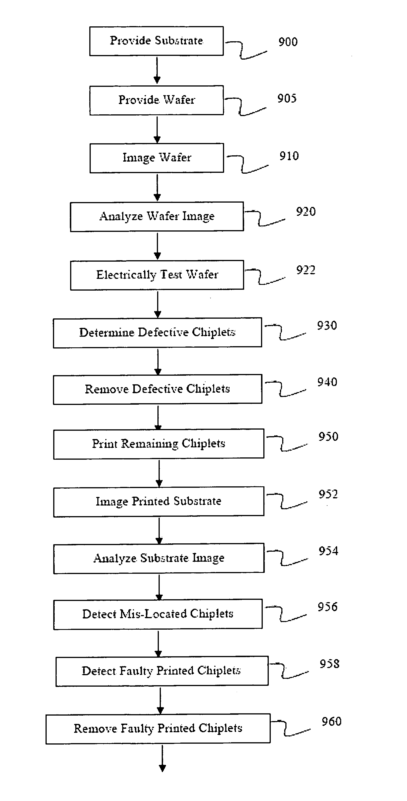
A large-format substrate with distributed control elements is formed by providing a substrate and a wafer, the wafer having a plurality of separate, independent chiplets formed thereon; imaging the wafer and analyzing the wafer image to determine which of the chiplets are defective; removing the defective chiplet(s) from the wafer leaving remaining chiplets in place on the wafer; printing the remaining chiplet(s) onto the substrate forming empty chiplet location(s); and printing additional chiplet(s) from the same or a different wafer into the empty chiplet location(s).

Description

CLAIM OF PRIORITY[0001]This application claims priority from U.S. Provisional Patent Application No. 61 / 242,955, filed on Sep. 16, 2009, in the United States Patent and Trademark Office, the disclosure of which is incorporated by reference herein in its entirety.FIELD OF THE INVENTION[0002]The present invention relates to large-format substrates with distributed, independent control elements and, in particular, to methods for fabricating such substrates with a high yield.BACKGROUND OF THE INVENTION[0003]Flat-panel display devices are widely used in conjunction with computing devices, in portable devices, and for entertainment devices such as televisions. Such displays typically employ a plurality of pixels distributed over a substrate to display images. Display devices are typically controlled with either a passive-matrix control employing electronic circuitry external to the substrate or an active-matrix control employing electronic circuitry formed directly on the substrate. Organ...

Claims


Application Information

Patent Timeline
Patent Type & Authority Applications(United States)
IPC IPC(8): H01L33/00H01L21/66
CPCH01L2227/323H01L27/3255H10K59/129H10K59/1201H10K71/70H10K59/00H10K59/123H10K59/131G01R31/28
Inventor BOWER, CHRISTOPHERMENARD, ETIENNEHAMER, JOHNCOK, RONALD S.
Owner X DISPLAY CO TECH LTD
Why Eureka
Try Eureka