
Laser scanning microscope and method for operation thereof

a laser scanning microscope and laser scanning technology, applied in the field of laser scanning microscope and the method for operation thereof, can solve the problems of affecting the accuracy of the individual scan, the risk of not exactly the same measuring point being scanned, and the bleaching of the sample, and achieve the effect of high speed

Active Publication Date: 2012-09-13
CARL ZEISS MICROSCOPY GMBH
View PDF8 Cites 6 Cited by
  • Summary
  • Abstract
  • Description
  • Claims
  • Application Information

AI Technical Summary

Benefits of technology

[0015]It is the object of the invention to provide methods and arrangements of the type mentioned above which allow a quantitative evaluation of images acquired by microscope with minimal error. In particular, the quantitative evaluation is possible at a high speed.
[0018]A color neutral splitter having a high splitting ratio such as 1000:1 or 100:1 can be used. A substantially higher dynamic range of intensity can be acquired in this way.

Problems solved by technology

However, the measurements are carried out consecutively, which leads to the following problems.
In the biomedical field:Long measuring times. Since scanning must be at least doubled, the measuring time is at least doubled.The risk that not exactly the same measuring points will be scanned in the individual measurements, e.g., due to vibrations and scanners which do not run in an exact manner.The sample is stressed to a greater extent due to the doubled scanning, which can lead to a bleaching of the sample.When viewing living cells, changes may occur in the cells, i.e., the sample, between individual measurements; that is, combining the observation of living cells with HDR is useful only to a limited extent with present-day methods.In current methods, a number of measurements are carried out consecutively and then calculated.
However, they are not suitable as a substitute for the photomultiplier tubes (“PMTs”).

Method used


Image

  • Laser scanning microscope and method for operation thereof
  • Laser scanning microscope and method for operation thereof
  • Laser scanning microscope and method for operation thereof

Examples


Embodiment Construction

[0031]It is to be understood that the figures and descriptions of the present invention have been simplified to illustrate elements that are relevant for a clear understanding of the present invention, while eliminating, for purposes of clarity, many other elements which are conventional in this art. Those of ordinary skill in the art will recognize that other elements are desirable for implementing the present invention. However, because such elements are well known in the art, and because they do not facilitate a better understanding of the present invention, a discussion of such elements is not provided herein.

[0032]The present invention will now be described in detail on the basis of exemplary embodiments.

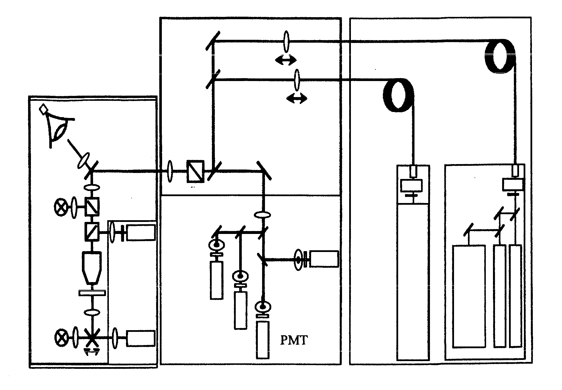
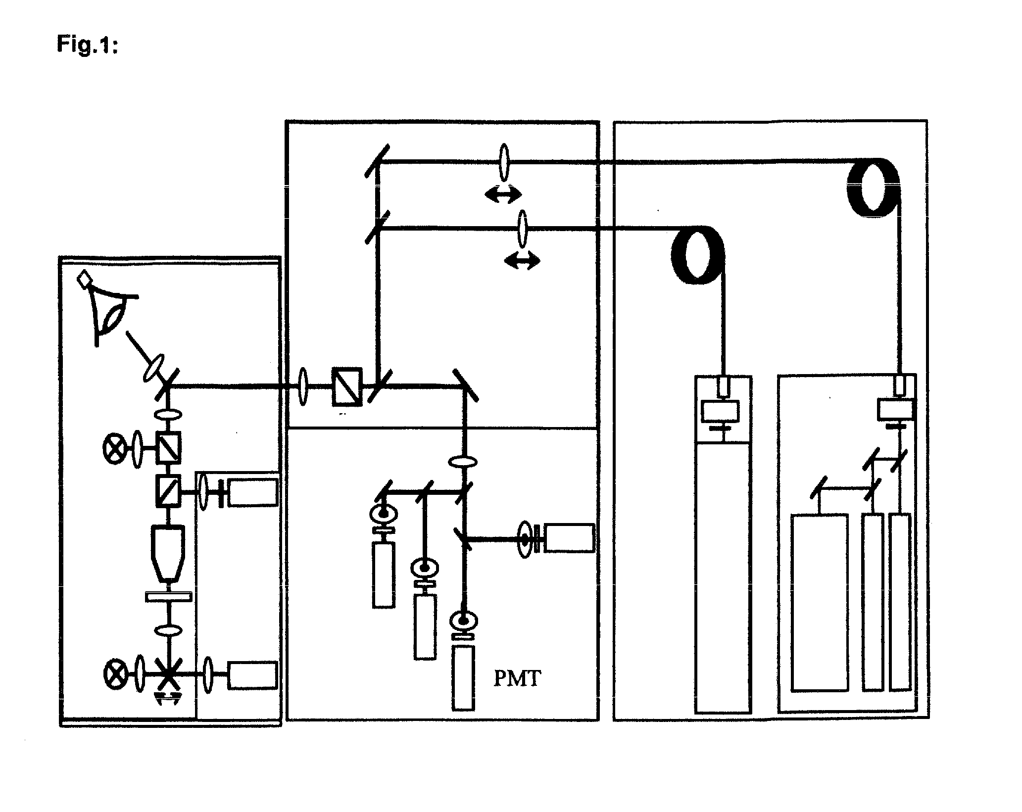
[0033]A beam path of a laser scanning microscope is shown schematically in FIG. 1. As is shown in FIG. 1, a laser scanning microscope (“LSM”) is basically made up of a plurality of modules: light source, scanning module, detection unit, and microscope. These modules are describ...


PUM


Abstract

Laser scanning microscope and method for the operation thereof having at least two detection channels which has at least one beamsplitter with a splitting of the sample light deviating from the 50:50 split and / or, with 50:50 split in the detection channels, has detectors with differently adjusted gain, or in at least one detection channel with equal light splitting has an additional light attenuator.

Description

[0001]The present application claims priority from German Patent Application No. DE 10 2011 013 614.2 filed on Mar. 8, 2011, the disclosure of which is incorporated herein by reference in its entirety.BACKGROUND OF THE INVENTION[0002]Materials samples and biomedical samples frequently have high contrast ratios. These high contrast ratios cannot be covered by a single measurement, for example, with the Zeiss LSM 700. For this purpose, there are HDR (High Dynamic Range) methods in which the measurement result is composed of a number of individual measurements with different illumination intensities or detector sensitivities (PMT gain). However, the measurements are carried out consecutively, which leads to the following problems.[0003]In the field of materials (topography measurement):[0004]Long measuring times. Since scanning must be at least doubled, the measuring time is at least doubled.[0005]The risk that not exactly the same measuring points will be scanned in the individual mea...

Claims


Application Information

Patent Timeline
Patent Type & Authority Applications(United States)
IPC IPC(8): G01B11/24H04N23/75H04N23/76
CPCG01N21/6458G02B21/0076G02B21/008G06T2207/20216G06T2207/20208G06T2207/10061G06T2207/10144G06T5/50
Inventor LANGHOLZ, NILSHUHSE, DIETER
Owner CARL ZEISS MICROSCOPY GMBH
Learn More