
Catheter with radiopaque coil

Inactive Publication Date: 2012-09-13
ABBOTT CARDIOVASCULAR
View PDF5 Cites 18 Cited by
  • Summary
  • Abstract
  • Description
  • Claims
  • Application Information

AI Technical Summary

Benefits of technology

[0006]The present invention is a catheter or catheter delivery system that incorporates a coil made from a radiopaque material that can be inserted between layers of a multi-layer catheter body. The coil is placed, for example, over a first layer of a multi-layer catheter body, and then a second layer of material is formed over the first, capturing the radiopaque coil between the two layers. Where the coil is disposed at, for example, the beginning or end of the working length of the balloon, the physician can accurately determine the precise location that the balloon needs to be positioned under fluoroscopy by locating the coil, which in turn identifies the beginning (or end) of the balloon's working length.

Problems solved by technology

Incorporating markers into the catheter's or balloon's structure can be expensive, and the markers can become dislodged when the catheter is torqued during delivery or when the catheter's balloon expands.

Method used


Image

  • Catheter with radiopaque coil
  • Catheter with radiopaque coil
  • Catheter with radiopaque coil

Examples


Embodiment Construction

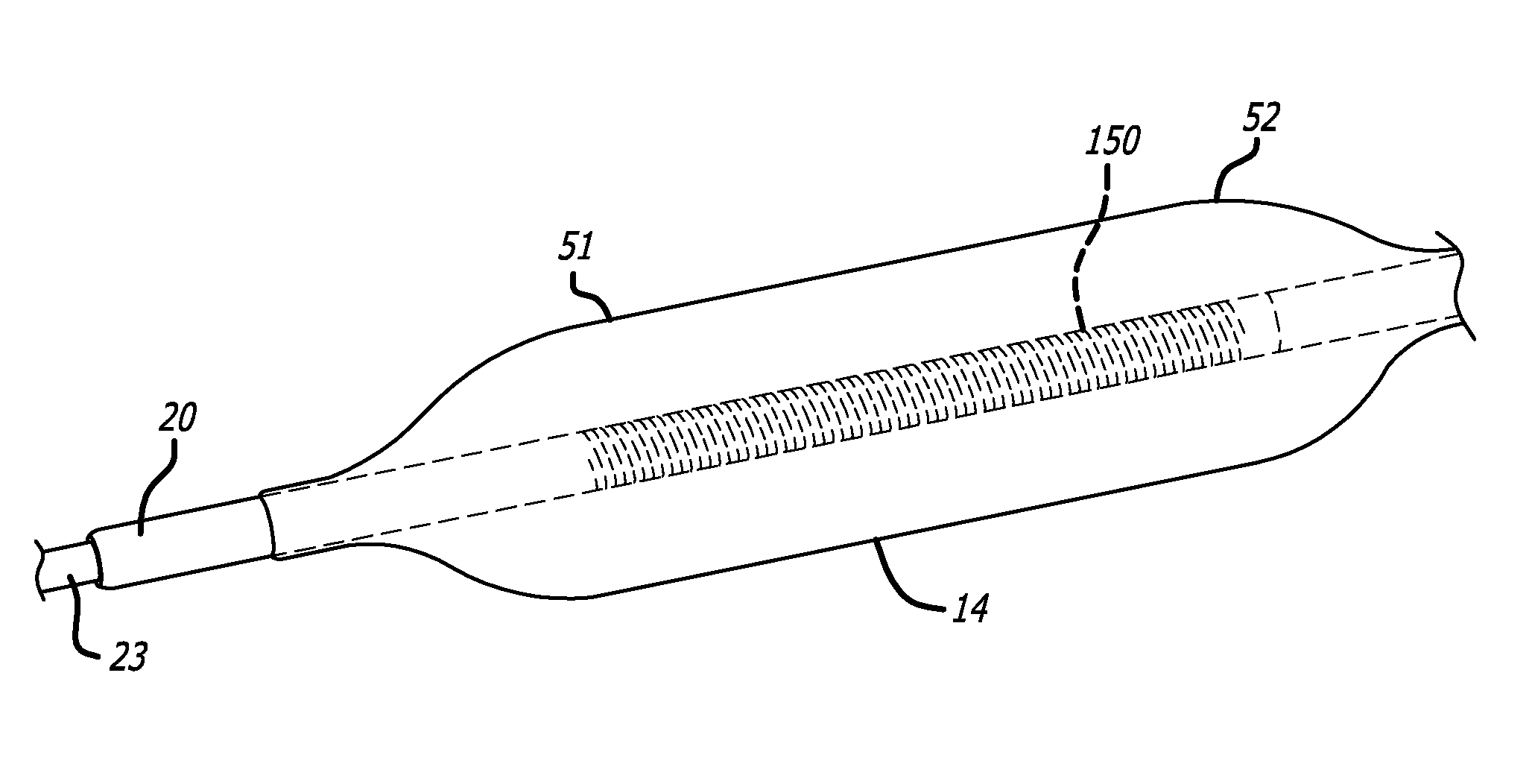
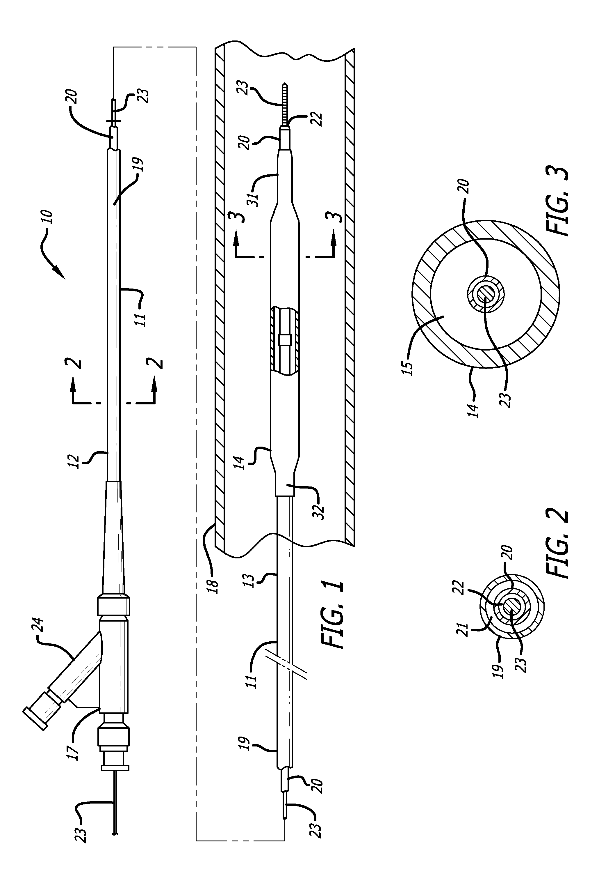
[0016]FIG. 1 illustrates a balloon catheter of the type that can benefit from the present invention. The catheter 10 of the invention generally comprises an elongated catheter shaft 11 having a proximal section, 12 a distal section 13, an inflatable balloon 14 formed of one or more polymeric materials on the distal section 13 of the catheter shaft 11, and an adapter 17 mounted on the proximal section 12 of shaft 11. In FIG. 1, the distal portion of the catheter 10 is illustrated within a patient's body lumen 18, prior to expansion of the balloon 14.

[0017]In the embodiment illustrated in FIG. 1, the catheter shaft 11 has an outer tubular member 19 and an inner tubular member 20 disposed within the outer tubular member defining, with the outer tubular member, an inflation lumen 21. Inflation lumen 21 is in fluid communication with the interior chamber 15 of the inflatable balloon 14. The inner tubular member 20 has an inner lumen 22 extending therein which is configured to slidably re...


PUM

PropertyMeasurementUnit
Fractionaaaaaaaaaa
Densityaaaaaaaaaa
Molecular weightaaaaaaaaaa

Abstract

A balloon catheter having a radiopaque coil embedded in the catheter's body corresponding to a landmark of the balloon or other location on the catheter body. The radiopaque coil can be viewed under fluoroscopy to located the balloon or other structure of the catheter. The coil can be readily inserted in the manufacturing process by inserting it between two layers that form the catheter body, and then sealing the coil inside the catheter at the desired location. This facilitates both the manufacturing process and prevents the marker from being dislodged during the manufacturing, navigation, or inflation process.

Description

BACKGROUND[0001]This invention generally relates to intravascular balloon catheters and systems for performing percutaneous transluminal coronary angioplasty (PTCA) and / or stent delivery, and more particularly to a catheter delivery system that uses a radiopaque coil in the catheter structure to provide a visual indicator in the system showing where a part of the catheter is located within a body lumen.[0002]PTCA is a widely used procedure for the treatment of coronary heart disease. In this procedure, a balloon dilatation catheter is advanced into the patient's coronary artery and the balloon on the catheter is inflated within the stenotic region of the patient's artery to open up the arterial passageway and thereby increase the blood flow there through. To facilitate the advancement of the dilatation catheter into the patient's coronary artery, a guiding catheter having a pre-shaped distal tip is first percutaneously introduced into the cardiovascular system of a patient by the Se...

Claims


Application Information

Patent Timeline
IPC IPC(8): A61M25/10B32B38/10B32B37/02A61M25/098B23P17/04A61F2/958
CPCA61M25/1036Y10T29/49826A61M25/0108A61M25/104A61M25/0012Y10T156/1062A61F2/958
Inventor HASLINGER, THOMAS
Owner ABBOTT CARDIOVASCULAR
Features
  • Generate Ideas
  • Intellectual Property
  • Life Sciences
  • Materials
  • Tech Scout
  • Unparalleled Data Quality
  • Higher Quality Content
  • 60% Fewer Hallucinations
Learn More