Surgical forceps having engagement in a groove

a technology of forceps and grooves, applied in the field of forceps, can solve the problems of constant maintenance and clamping force, and achieve the effects of enhancing the possible use of forceps, easy rotation, and simplifying design

Inactive Publication Date: 2012-09-13
OLYMPUS WINTER & IBE
View PDF9 Cites 5 Cited by
  • Summary
  • Abstract
  • Description
  • Claims
  • Application Information

AI Technical Summary

Benefits of technology

[0010]According to embodiments of the invention, it is advantageous that the forceps jaw is rotatably supported with respect to the actuating handle, thus enhancing the possible uses of the forceps.
[0011]Known surgical forceps having a rotatable forceps jaw have the disadvantage that the actuating force is transmitted from the actuating handle to the distally situated forceps jaw, and therefore the counterforce transmitted via the shaft passes through a rotary bearing, which is blocked by this force. Thus, according to the prior art, rotating the forceps jaw while transmitting the actuating force at the same time can be achieved only by rotating the complete forceps. In the forceps according to the invention, the shaft is free of axial forces, even when a closing force is applied between the jaw parts, so that the jaw is able to easily rotate. According to embodiments of the invention, it is advantageous to provide the rotary bearing at the distal end of the shaft. Co-rotation of the shaft while the forceps jaw is rotating is thus avoided. Rotational friction of the shaft, for example in a trocar seal, is avoided in this way. In addition, curved shafts, which usually are not rotatable as a whole at the installation site, may be used.
[0012]According to embodiments of the invention, particularly advantageous rotational control from the actuating handle is achieved via the actuating rod, thus simplifying the design.
[0013]According to embodiments of the invention, the shaft of the forceps is advantageously curved. Such a curved shaft simplifies handling of the forceps during minimally invasive surgical procedures.

Problems solved by technology

A disadvantage of this known design, however, is that for closing forces to be applied by the forceps jaw, for example when a needle holder is used, the clamping force for holding the needle must be continuously maintained by applying an actuating force via the actuating rod.
Known surgical forceps having a rotatable forceps jaw have the disadvantage that the actuating force is transmitted from the actuating handle to the distally situated forceps jaw, and therefore the counterforce transmitted via the shaft passes through a rotary bearing, which is blocked by this force.

Method used


Image

  • Surgical forceps having engagement in a groove
  • Surgical forceps having engagement in a groove

Examples


Embodiment Construction

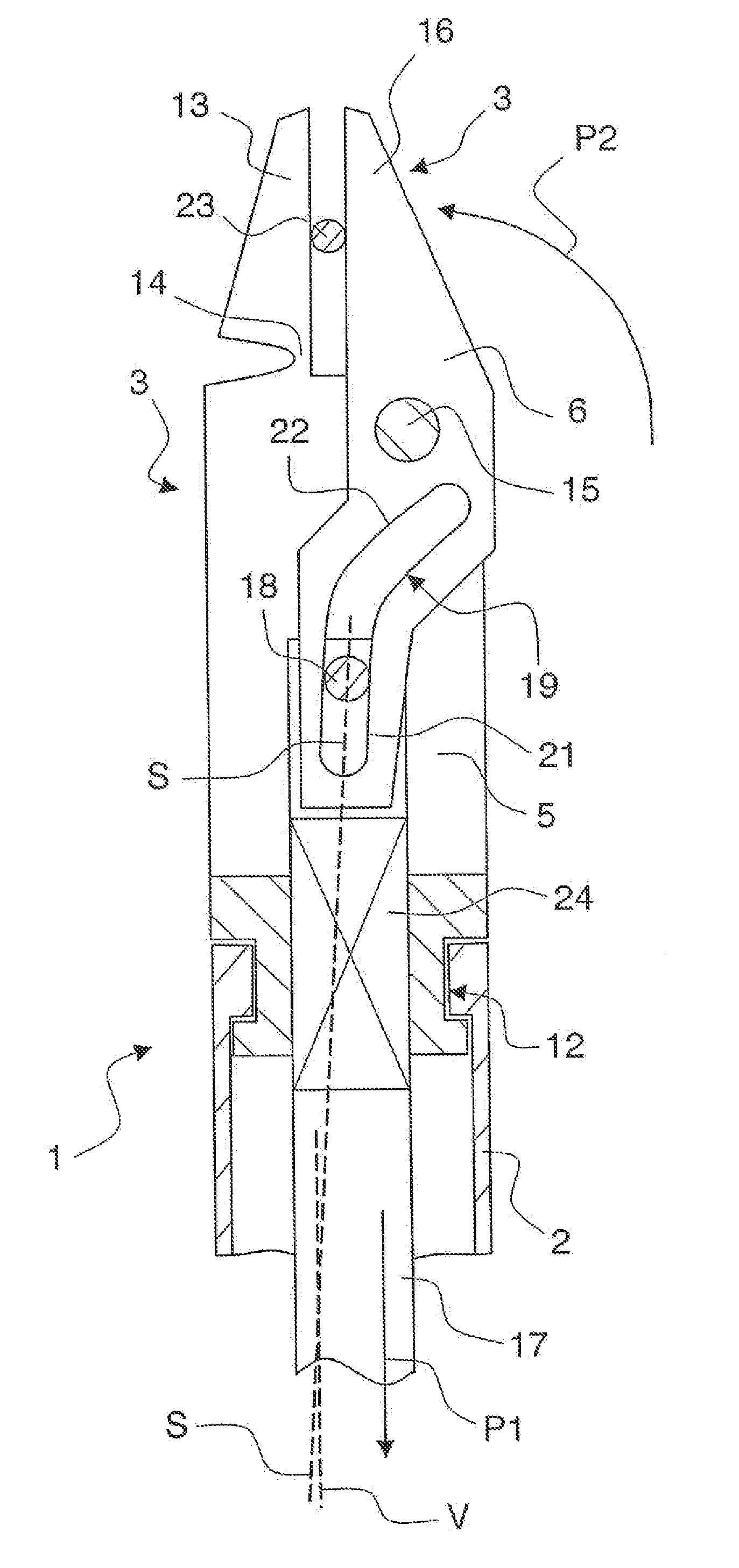
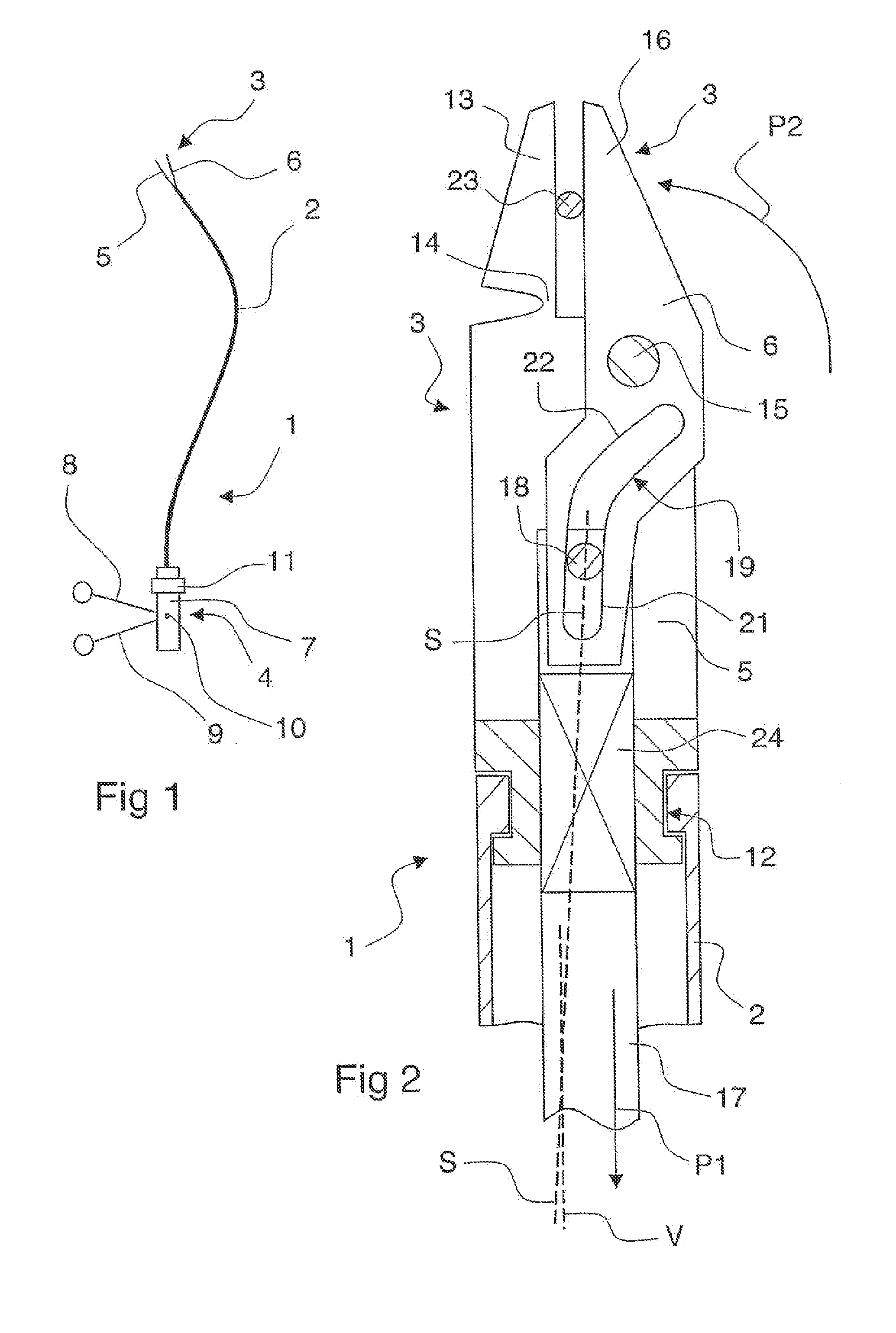
[0017]The forceps 1 illustrated in a side view in FIG. 1 are designed in particular for laparoscopic use. The forceps have an elongated, curved shaft 2 having a forceps jaw 3 at its distal end and an actuating handle 4 at its proximal end.

[0018]The forceps jaw 3 has two jaw parts, one jaw part 5 being stationarily attached, and the other jaw part 6 being pivotably attached, to the shaft 2.

[0019]The actuating handle 4 has a main body 7 on which two finger grips 8, 9, each having a holding ring as illustrated, are supported about an axis 10. In addition, a rotating ring 11 is supported on the main body 7.

[0020]The distal end region of the forceps 1 in FIG. 1 is illustrated in FIG. 2 in greatly enlarged form.

[0021]The shaft 2 has the cross-sectional design of a tube. As shown in the sectional illustration, the shaft is rotatably supported, via a rotary bearing 12, on the proximal end region of the stationary jaw part 5. The stationary jaw part 5 extends from the rotary bearing 12 to it...


PUM


Abstract

Surgical forceps are provided having an elongated shaft which at its distal end bears a forceps jaw having two jaw parts which are movable relative to one another, and at its proximal end bears an actuating handle which by means of a longitudinally displaceable actuating rod that passes through the shaft controls the relative motion of the jaw parts via the engagement of at least one cam on the forceps jaw or on the actuating rod in a groove which is inclined at an angle with respect to the direction of displacement of the actuating rod on the shaft or on the forceps jaw. The groove is provided, at least in one section, with an angle of inclination which is smaller than the angle of inclination up to which self-locking in the groove occurs.

Description

BACKGROUND[0001]I. Field of the Invention[0002]The invention relates to forceps.[0003]II. Description of the Related Art[0004]DE 195 21 257 A1 discloses generic forceps having a groove in engagement with a cam and situated at a fairly large angle of inclination with respect to the direction of displacement of the actuating rod. The groove engagement may transmit motions in both directions. Due to the large angle of the groove with respect to the direction of displacement, there is no self-locking. Large changes in the angle of the moved jaw part may be quickly made on account of the large angle.[0005]A disadvantage of this known design, however, is that for closing forces to be applied by the forceps jaw, for example when a needle holder is used, the clamping force for holding the needle must be continuously maintained by applying an actuating force via the actuating rod. For this purpose, in the prior art it is known to provide a fixing device in the actuating handle.SUMMARY[0006]E...

Claims


Application Information

Patent Timeline
Patent Type & Authority Applications(United States)
IPC IPC(8): A61B17/28
CPCA61B17/062A61B17/29A61B2017/2922A61B2017/2946A61B2017/2937A61B2017/2941A61B2017/2936
Inventor AUE, THOMAS
Owner OLYMPUS WINTER & IBE
Why Eureka
Try Eureka