Power umbilical

a technology of power cables and umbilical cords, which is applied in the direction of cable junctions, cable terminations, cable installations on floats, etc., can solve the problems of limiting the depth of sea depth where the umbilical can be deployed, poor load carrying capacity, and add considerable weight to the umbilical cords, etc., to achieve easy withstand, reduce load, and high strength

Active Publication Date: 2012-09-20
TECH FRANCE SA
View PDF10 Cites 28 Cited by
  • Summary
  • Abstract
  • Description
  • Claims
  • Application Information

AI Technical Summary

Benefits of technology

[0015]One aspect of the invention is to replace the copper conductors of the power cables by conductors made of a high strength material having a tensile strength to density ratio greater than copper, for example, high strength aluminum grades, metal matrix composites, or carbon fiber composite reinforced conductors. Such conductors are used for overhead power transmission (see U.S. Pat. No. 6,180,232) and are strong and light enough to be able to withstand their own suspended weight in water. Furthermore, these conductors can be used as load bearing elements which partially withstand the tensile loads applied to the umbilical. This solution decreases the tensile loads applied to the other load carrying components (steel pipes, steel or composite ropes, steel or composite rods, steel or composite armors), and therefore increases the tensile strength of the umbilical and / or makes it possible to reduce its weight by removal of some of the other load carrying elements.
[0030]The second aspect of the invention is that when a high strength power core and / or cable is included in an umbilical, it is advantageous to mechanically connect the high strength conductor to the end termination of the umbilical, i.e. in the event of load share or self support of the cable / core. This is a means whereby the tensile strength of the conductor can be mechanically coupled to the end termination, while it is also electrically isolated from earth or ground potential.

Problems solved by technology

These heavy copper conductors add considerable weight to the umbilical and have very poor load carrying capacity, thus limiting the sea depth that the umbilical can be deployed at.
Unless protected, these electrical conductors may be damaged by excessive elongation or crushing especially under severe conditions such as in deep water and / or dynamic umbilicals.

Method used


Image

  • Power umbilical
  • Power umbilical
  • Power umbilical

Examples


first embodiment

[0058]An example of an umbilical hang-off termination according to the present invention utilizing the insulator in compression is illustrated in FIG. 5. The primary hang-off termination 10 of the umbilical 1 includes the termination of steel tubes, steel armors and / or other tensile strength elements. Those elements are anchored within the primary hang-off termination according to well-know prior art solutions. The primary hang-off termination may be filled with a hard setting compound, such as an epoxy resin, as disclosed in WO08037962.

[0059]The power cables 2 extend through the primary hang-off termination 10 without being fully anchored to it. The upper end of each core of each power cable 2 is fully anchored to a secondary hang-off termination 12, as illustrated in FIG. 8. Each power cable core is strongly attached to a respective special ferrule 14. The ferrules 14 are anchored in the secondary termination 12 via a cavity 13 defined by a housing 13″ and filled with a hard setti...

second embodiment

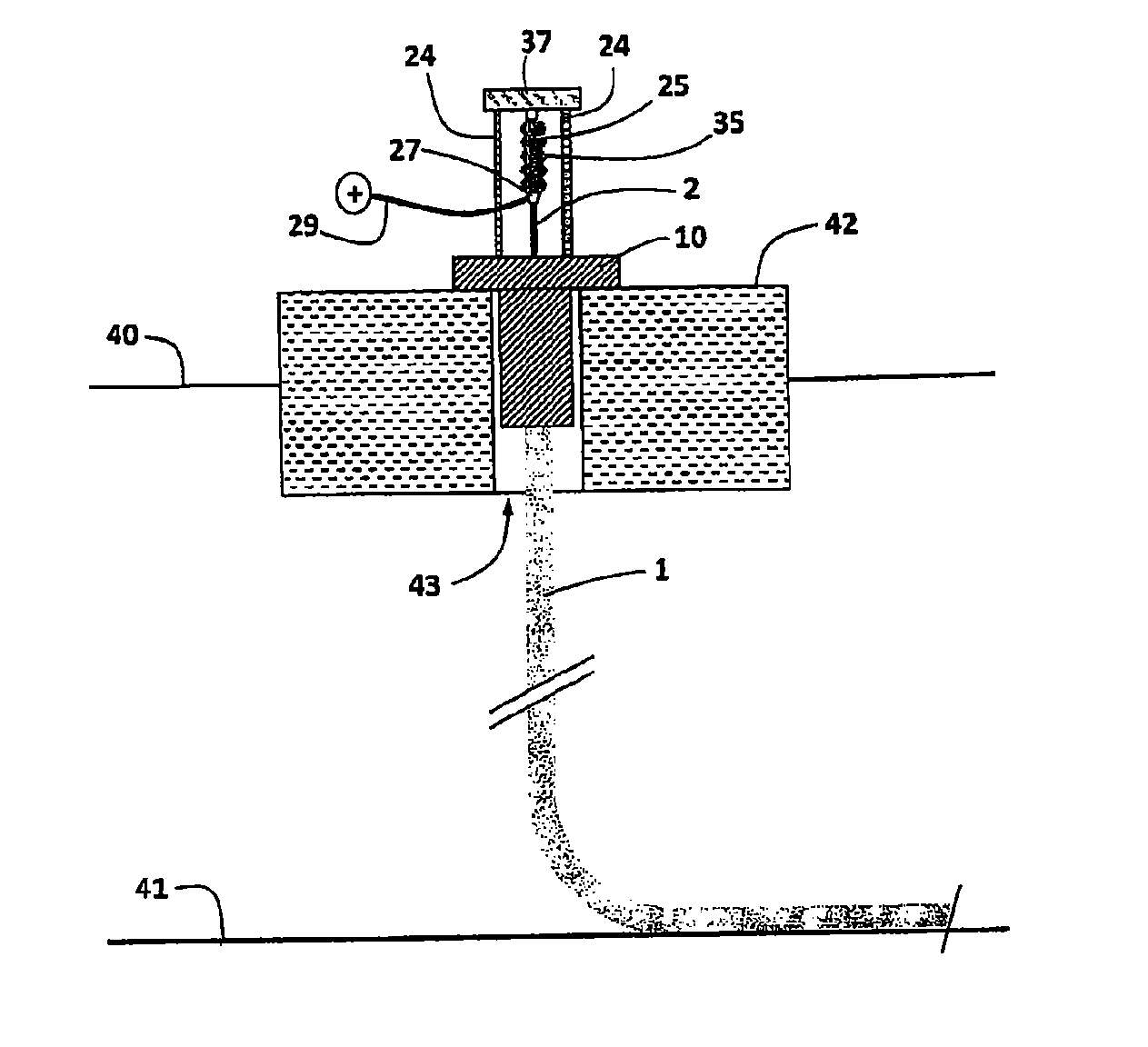
[0063]An example of an umbilical hang-off termination according to the present invention utilizing the insulator in tension is illustrated in FIG. 9. This shows the principle of how the insulator 25 is attached via an anchoring feature 26 to the secondary hang-off termination 37 and how the power cable 2 conductor is attached to the opposite end of the insulator using a connection ferrule 27. Access to the external electrical system is also made via the connection ferrule 27.

[0064]An example of how the conductor connects to the secondary hang-off location via an insulator according to the second embodiment of the present invention utilizing the insulator in tension, is illustrated in FIG. 11. This shows the principle of how the insulator 25 is attached via an anchoring feature 26, and how the power cable conductor 2 is attached to the opposite end of the insulator 25 using a connection ferrule 27. Access to the external electrical system 29 is also made via the connection ferrule wh...


PUM


Abstract

An umbilical for use, for example, in deep water applications includes a plurality of power cables and may include other elements bundled together and within a sheath. An end termination at each of the power cables or at a plurality of the power cables includes a resin ferrule around the cable at the end termination and provides a connection between the cable and an installation to which the umbilical is connected.

Description

RELATED APPLICATION[0001]This application claims priority to U.S. Provisional Application Ser. No. 61 / 265,188, filed Nov. 30, 2009, entitled POWER UBILICAL, the entire disclosure of which is incorporated herein by reference in its entirety.BACKGROUND OF THE INVENTION[0002]The present invention relates to an umbilical or power cable that is used in an offshore application such as oil and gas field developments, subsea pumping, processing and renewable energy installations.[0003]An umbilical consists of a group of one or more types of elongated active umbilical elements, such as electrical cables, optical fiber cables, steel pipes and / or hoses, cabled together for flexibility, over-sheathed and, when applicable, armored for mechanical strength. Umbilicals are typically used for transmitting power, signals and fluids (for example for fluid injection, hydraulic power, gas release, etc.) to and from a subsea installation.[0004]The umbilical cross-section is generally circular. The elonga...

Claims


Application Information

Patent Timeline
Patent Type & Authority Applications(United States)
IPC IPC(8): H02G15/02
CPCH02G9/12H02G15/14H02G15/076
Inventor MADDEN, DAVID
Owner TECH FRANCE SA
Why Eureka
Try Eureka